(Log in to disable ads.)

  • DIY
  • Yeti and GTP's Combo Build

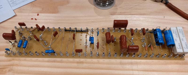
Right, so I've put together a first pass of the circuit (still needs a proper review so there are likely to be mistakes). The Pre-Amp is more or less a direct clone of the Quick Rod circuit, although I am tempted to tweak that clean channel a little more sparkly (possibly change the tone stack to something a little more Fendery).

The Aux page has the circuitry for the footswitch controller (using optocouplers... more reading required) and the FET FX loop. Both of these will be built on veroboard, probably with the jacks mounted straight on the board, which will fix the board against the back panel of the chassis (now that I look at this, the FET option, may not save that much space over an extra valve... but it will be cheaper). My current design has duplicate buttons on the amp and the footswitch so that channel, gear, etc. can be controlled from either... I'm not 100% sure if this is going to stay however because those switches add quite a lot of real estate and I'm worried about the wires running backwards and forwards across the amp, although this would be minimised if they were mounted on the back, near the footswitch plugs...

The Output stage is a combination of the Quick Rod inverter and a relatively generic cathode biased EL34 circuit (although, actual value of bias resistors may change). It also has a Post Phase Inverter Master Volume thrown in for good measure.

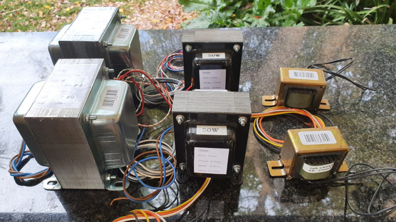
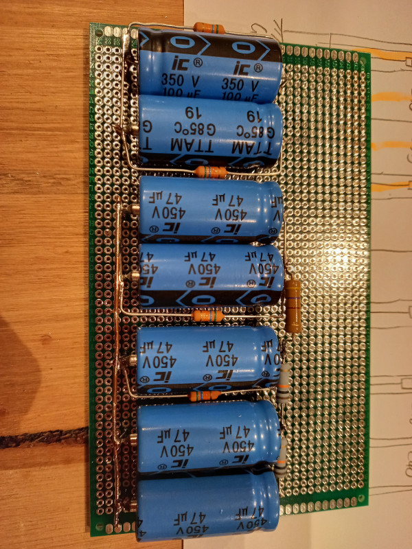
Power supply is relatively generic except for the added Power Scaling, I've included the chip number that I used for my 15W black face clone, if I remember correctly it should be able to handle the current but I will need to double check, current plan is to mount this directly onto the chassis for heat conducting. I'm aiming for the voltages specified on the QR schematic and may need to teak a few resistor values to get them but in my (limited) experience these aren't that critical for the pre-amp tubes, provided your power amps have the correct voltage. I've also included some pretty beefy capacitors and an over-sized power transformer. The reason for this is that I want a properly stiff power supply for this amp to prevent it from loading down. Incidentally, I've gone with a half wave rectifier simply because of the transformer I've found, if we get one wound, I'll probably look at halving the voltage and going bridge rectifier.

Next it's on to the layout, which will help us size the chassis and ultimately the head itself... this is quite a complex beast, so I expect it to be large.

p.s. on a side note, everything I know about grounding I learnt from the Valve Wizard. (http://www.valvewizard.co.uk/Grounding.html) For this amp, I'm planning on using the star grounding layout with chassis connections only at the AC plug and the input jack. Heater wires will be earthed via center tap on the transformer.

Hmmm... we also need to come up with a name for this project.

Right... starting to think layouts... this is a busy amp!

So here's what needs to go in...

Top:
Power Transformer
Choke
Power Capacitors (probably... may go inside)
4 Pre-amp Tubes
2 Output Tubes
Output Transformer

Back:
OD1/2 button
Channel button
Foot Switch Plug 1
Foot Switch Plug 2
Send Level
Send Jack
Return Jack
Return Level
Speaker Jack
Speaker Impedance Selector
Standby Switch
Power Switch
Fuse
Power Socket

Front:
Input Jack
Clean Gain
Clean Treble
Clean Bass
Clean Volume
OD Gear
OD Gain
OD Treble
OD Mids
OD Bass
OD Volume
OD Solo
Master
Presence
Power Indicator

... right... here we go

Nice. That is busy. Will be curious to see how it fits. At least we have some options if we need to reduce hardware

    First pass layout is done. There are some things that I'm not 100% happy with (e.g. the proximity of the FX loop board to the tube beneath it) but I think that it's a reasonable proof of concept. Dimensions for this chassis are 525x200x60.
    Current plan is to make the build of this true point to point and use as many terminals on the tube sockets and controls as possible. Intending to use turret board for intermediate points.

    I think the next step will be to lay out the two veroboards because at this point their sizes are pure thumb suck.


    Ha! Thats perfect! For reference, my vox head is 470x170x65.. so thats not bad at all.. puts it at just under the big marshall heads.

    So cool to see it coming together. Well done bud. Apologies for not assisting.. but my electronics knowledge is as good as my ability to speak russian.

    So.. we are dumping the standby? ??

    guidothepimmp Haha, your bit will start soon.
    Incidentally, this puts it almost exactly the same size as my bassman... although it will be a lot busier. ?

    So yeah... standby... out of interest, what does everyone else think of a standby on a valve amp?

    a month later

    So... on behalf of Yeti who is the brains behind this all.

    The initial design is largely done. We have souced quotes for transformers which we will likely move to ordering in the next week. Then a revisit to check the components and layout so we can finalise the chassis. I have reached out to a few folk regarding getting the chassis made up.. looking at aluminium or mild steel sheets. We are aiming to bed down the layout so that hopefully we can bed down where the holes go so that the cnc can do it.

    Once the chassis is sorted.. i will start moving on the head cabinet to house these. Reached out to some contacts for tolex.

    Sooo... i think it is going along nicely.. if Yeti has the patience.. im am hoping to wire and solder mine alongside him to learn something in the process. But we will see how it goes ?

    Looking good. I understand Aluminium would be better for heat dissipation.

    4 months later

    Weeeeeellll, this is grinding slowly back to life.
    We've just received the transformers we ordered back in Feb... 15kg between the two amps, that's a lot of iron and copper. These were custom made for us by Peter Souris Transformersin the Johannesburg CBD.

    I've also done a preliminary layout of the circuit boards, going to take another pass or two before I post but we're getting there and I've made some good progress on specing the components and should be ready to place the order quite soon.
    Also, with the transformers in hand, we can finalise the layout and start ordering the metalwork.

    Nice. Could you share the transformer / choke specs and ballpark cost?

    You wanted opinions on standby switches, I am ignorant about amps, but feel it is beneficial. I have two amps without, one is the 5F1 -alike with a tube rectifier. The current ramp-up on it is, well, not benign. The Laney Cub 10 has silicon rectification, not sure how they control the current inrush. Just seems better to switch to standby when unplugging stuff, or waiting for the President to finish the latest lockdown speech.

    • Yeti replied to this.

      modulator
      Specs and prices (ex Vat) as follows:

      Power transformer - R840
      Primary - 240V
      Secondary 1 - 345V 400mA
      Secondary 2 - 6.3V (with center tap) 5A

      Choke - R180
      5H 400V 120mA

      Output transformer (suitable for push-pull 6L6) - R890
      Primary Impedance - 3200 Ohm
      Secondary Impedances - 4, 8 and 16 Ohm
      Power - 50W

      These were largely based on these Hammond transformers:
      Power - 290GX ~ R2,008
      Choke - 194F ~ R441.59
      Output - 1750N ~ R1503

      So I hear you on the unplugging... thing is, the standby switch pulls the high voltage off tubes' plates... which is a pretty drastic method of muting. If that's the goal (and given that we're talking scratch designed amps) then I'd rather add a mute switch that shorts out the inputs.

        Thanks. I have no idea whether the potential and current inrush to the valves at startup is bad or not, I know my father's old Philips gram had no standby, and I remember him always switching on and waiting a few minutes before turning up the volume. I have that Philips here, as a youth I removed the valves and later the speaker (one really should become a Yedi and see into the future) and I really have to get myself in gear and fix it, or get someone to fix it. Uh, maybe first check if it does FM... Nevermind, with a vinyl-friendly turntable it should be fun, even if it is only a milliWatt and mono.

        On the other hand, my ex-wife has a Stereo set here, and she says as kids they never worried about valve do-do-not's (did not know) and always switched on and rocked. Still goes, original components. I would love to fit a decent turntable in that one. So, no, I cannot really advise on standby switches.

        Have fun.

          According to my reading, the standby switch was added by one of the big guys (Fender?) because they had cut costs on the reservoir capacitors and they couldn't handle the inrush. I can't remember the details but I know that there are some builders who have never installed them and other who do so only because the peoples demand it. As far as I know, modern caps are solid enough that even the cheap ones are more than potent enough.
          I also believe that it's good practice in some high frequency applications... but guitar amps don't play in that range.

            3 months later

            This project isn't moving fast... but it is moving.
            Just received the delivery from Tone Tubes. Most of the more conventional electronics should be here next week.

              3 years later

              I suppose I can update this seeing as we have progressed 😀

              So it was with some dismay that I noted that the last update here was 2020, and to be fair.. yes. We were largely inactive on this for the better part of 2 to 3 years. That said... last year we picked this up again and basically have a functional amp, and it is indeed a firebreather amp as envisaged. Here is how we went along picking up from the hardware as posted above.

              So first up was wiring up the power supply. We ummed and ahhhed about whether to go with a dogbox, or simply to mount it in the chassis. We eventually opted for the latter. The caps were mounted on a small PCB and eventually fitted in the chassis using the Transformer bolts as risers on the inside of the chassis

              Once that was done, we installed the turrets on the board and got to soldering in the caps and resistors on the turret board for the preamp

              In parallel to this, we realised we best get going with the chassis, so we drew up some images in a freeware CAD software and got some chassis cut and bent. due to cost, we went with 1mm steel (this was tough on our drill bits in the end, but alls well that ends well)

              Then using a layout diagram that Yeti worked on, we cut and drilled holes... we eventually finished the chasses in a blue/black mix that Yeti came up with. Looks pretty darn smart we think..

              In the meantime and in parallel to wiring in the wires, we also did some work on building the head case from marine birch ply 18mm. We went with standard butt joints but reinforced these with dowels. Came out quite solid and square.


              The face plates we also drew up in a CAD software, and got those laser printed, and we opted for a red tolex which turned out quite nice.

              With a chassis and a case sorted, we could focus on finishing up the wiring, mounting the hardware to the chassis, and beginning with the installation of the transformers and power and preamp bits


              After checking and rechecking, we fired it up for the first time. Happily nothing popped. I did fry the two coupling resistors on the bias though.. so we upped the spec on those to 3w (from 0.5W).
              I would love to say it all worked perfectly out of the gate, but it didn't. The amp made a sound, just not a very pleasant sound, and so we embarked on the painful journey of fault finding/ tweaking. After a few days of some frustration, we did a deep dive into the circuit diagrams, and lo and behold, we found a few funnies. The bigger issues were a missing coupling cap in the preamp, some misaligned resisted values and a misrouted earth. Once these items were sorted out, we got that lush fire breathing overdrive we were expecting.. Pretty darn happy happy with the outcome.

              Are we finished yet? not quite. The amp is largely done and works well, we now need to finish making and wiring in the effects loop, and we also need to make the footswitch to drive this thing. This we will hopefully bed down in the next couple of weeks.

              modulator
              There are a few lumber suppliers here in Pretoria which are quite good. This 18mm ply i got from a place called Davidsons Discount Boards. Excellent service from them, I can highly recommend them.

              I see they have branches in the Cape and in KZN as well