(Log in to disable ads.)

Onward with my quest. My research indicated that all valve amplifiers are not alike. They differ in sound character due to design, components, and, of course, valve type. Who knew? I did not. Adding amps to my collection, my ears seem to like 6V6 power valves in simple low-Watt amplifiers, driven by low-output single coil Stratty guitars, with a bright, responsive speaker without ice-pick treble emphasis. With valve amplifiers, modifications (money, expertise) can change any valve amplifier into another type of amp. I have read up on mods for the HAZE series: Most are aimed at increasing gain to get to the legendary Marshall sound (which is?), and to add brightness to the overdrive channel (yes please, within reason). No mods to “tame” the clean channel, though – all to add more gain/grit (?). There is one sensible mod, add a Master Volume for the clean channel. Sure. There may be many more mods, but I really do not understand what the people are talking about, what this and that capacitance and resistance do to the whatever circuit giving that and such tone. Most of these mods are done to add gain and punch and volume and such. Not what I need. A re-design (re-voicing) is what I need, without all the IC junk, on a turret board. Any volunteers?

Seeing as I know nothing about the working/design of amplifiers, sorting out suitable modifications by myself is not going to happen (soon). I shall have to study Rob Robinette’s pages in detail. Being a PCB design, swapping around components will not be fun either. One could snip a capacitor leg here and there, but to re-soldering will be a hassle. I shall only do that when I have the relevant “try this one” replacement, with a new original value component in hand, long legs, to fit/re-fit. Snip the old component at the body, leaving some leads for soldering on another one.

    7 days later

    They tell me valve amps have to be “biased”. I always took this to be something calculated at design stage, testing the bias and fine-tuning relevant resistors after assembly, to be done again when changing valves. More importantly, only to be done by valve amp experts and magicians. I was lead to believe that this is an art only handed down from father to son, in secret. Could well be. Many ways to test, maybe only one correct way. How do you do it?

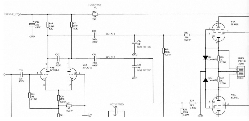
    This amplifier has two small trimpots (“VR1” and “VR2” on the circuit diagram, which I could find thanks to that modern marvel called “Internet”). The amplifier also has a “CON3” block on the PCB, looking like it requires a three-pin socket to go there. I would think the factory tech has just such a fitting to do the bias. The circuit diagram says “BIAS PIN 1, 3 39mV” above this “CON3” thing. The centre pin splits through two 1 Ohm resistors to the power valve cathodes. Now, posters on the net use mA as well as mV (both 39) for this setting, some sayning you need to bias for maximum 70% of plate dissipation, hence 39 mA, etc. Of course, the owner’s manual does not mention this rather important detail (“no user servicable parts inside”). And so, I would have destroyed my valves (if not damaged already) by doing just what the amp was built for – playing it.

    Easy-to-locate “CON3” .

    Conveniently placed VR1 and VR2. After initial adjustment to 35.4 mV. Schematic specifies 39 mV.

    I started by checking the bias. This should be correct from the factory, yes? Many internet posters tell horror stories. I concur. I clipped some alligator clip leads to the three pins, centre pin lead clipped to the earth probe of the multimeter, so all I had to do was clamp the positive probe alternatively into the leads from Pin 1 and Pin 2 as I go along, far away from the circuit itself. Less Stress.

    Leads clipped to the pins. Just enough space. This is a photo mock-up, no power.

    I was amazed to measure 75 mV for VR1 (Valve 5) and 48 mV for VR2 (Valve 4). The valves were being cooked in a bad way. Harsh sound indeed.
    Setting the bias is an “adjust VR1, adjust VR2, adjust VR1, adjust VR2” procedure. I set both close to 35.4 mV for a start. Too cool?

    (Must check HT and filament supplies as well. The circuit diagram shows the filament supply to Valve 1 to be separate from the rest, taken off the 12.6 VAC tap. Why? All three pre-amp tubes are ECC83-A? Oh, wait, I see. Pre-amp Valve 1 has DC filament voltage. Cute. Still is a noisy amp.)

    Does it sound better? Maybe. How would one be able to tell at my low volume? I can say, when it is warmed up well, it does appear to be “smoother”, and I perceive it to have less bass/more treble. (But, my ears seem to get more treble-sensitive as I go along. Or is it really the amp “opening up” as it gets warm? I find this to be true with my valve Hi-Fi as well.) Is this a result of cool bias resulting in “thin” tone? But, here’s the thing, turning the speaker away from me, opening the Normal volume to 5, with the OD channel set at Gain 5 and Master Volume 8 to match, with the guitar volume at 5 – 6 (Ibanez, linear pot?), covering my ears, the system reveals some interesting and exiting dynamics, which sounds like fun, and encourages me to keep on making noise. It did not have that character, before. Fun as it may be,
    1. it is beyond way too loud, and besides,
    2. I cannot play well enough to exploit this newfound tone.

    I really do need to explore this, if an attenuator does not work, I see myself in the market for a smaller Marshall (DSL 1, 5 or 15? Other, better options?), suitably speakered and modded. (Rob Robinette has a 1 Watt JCM 800 (and 22 Watt) circuit on his site, but after the 5F1 build, I am not feeling in the mood to go that route. Would be fun, though.)

    I am still amazed by this amp’s volume. I have a 15 Watt Ibanez TSA15H, which Internet posters agree is weak in volume (it is), and the small (ha) 5F1 build, which gets to window rattling volumes, but this Marshall Haze 40 is, well, very loud when I plug the Ibanez into it.

    hi

    I would suggest you get hold of JP Le Roux at lerouxampworks with a view to buying one of his great little amp designs. He will happily supply to suit the speaker of your choice and probably have some good advise re valve amps generally.

      modulator a 5w amp is not that much quieter.. wound up i mean.

      The only thing i find that helps is an attenuator. Even then. The amp gets to quarter volume.. thats pushing some 95db. When i wind back the master volume.. that gets to 80db which is my bedroom level.

      Should actually measure the vokume at a garage days

        JGP, such an amp may well cost more than my entire collection, I would not be able to go audition it, and the final speaker choice would only be possible after completion and testing with a known speaker. I would like to look through his designs though, someday. As for advice, still waiting...

          guido, I wonder if a 1 Watt amp would be good - not enough headroom maybe. (OK, the speaker sensitivity measured at 1 Watt thing aside - different guitars, different environment, tone perception, etc. Hey, everybody keeps on telling everybody else 3 dB is almost not noticeable, but they also recommend a 97 db speaker over a 95 dB speaker for more volume and more headroom and less distortion...) Seems like one requires a bit of volume to have fun anyway, unless the amplifier design would allow the sweet tone at low volumes. Including cleans and overdrive. Looking for that one. 5 Watt can be pretty loud, yeah. You should really poke a dB meter at it, and report back with details such as speaker sensitivity, estimated (measured?) amp output to speaker, guitar pickups, and so on.

            Ive never played or heard a 1w amp in the flesh.. so difficult to gauge. The smallest ive had was a 5watter. I really didnt get along with it. Had 1 decent sound.. but cranked.. nothing. I still dont know if it was the amp.. or if it was the 10inch celestion in the amp. I always meant to play it through a 12 incher but alas. Never got to it.
            When my amp guy was explaining my amp to me, he mentioned the pots having a sweet spot as opposed to the volume needing to be a certain volume for the sweet spot. Each pot was slightly different in where that sweet spot was. Basically he would sweep the pot min through max and there was apoint where there was a noticeable tonal or volume swell. This is the case on bass.. treb.. mids.. gain etc. His suggestion was to find that sweet spot on all the pots, then to dial back the master volume accordingly. Sounded bloody great. Was also bloody loud. The attenuator made by JP does a good job of reducing the volume to reasonable level.

            I got rid of all the small amps because headroom was an issue. My smallest valve amp is an orange terror. It has the the 15w and 7w setting. The vokume difference between the 2 settings is a few db. Noticeable.. but not significant in my opinion. Headroom and gain was more noticeable. I will have a look see at the speakers.

              3 months later

              I tested the amplifier with the single coil Strat-alike as well, lower output pickups, potentially brighter sounds. The lower output pickups do allow me to set the amp volume knob higher, and the sound is just what one would expect from single coils: Bright, twangy, with the “quack” in positions 2 and 4 crystal clear. The speaker is fine. Working at “small venue” volume levels, it is fun. The tone really is thin. Playing around with the treble controls on the amp and guitar richens up the tone, but I would say, thin. It needs body. Overdrive channel is fun, at higher volume, and the Normal channel is bright, some would say glassy clean. No fun when turned down to very low “bedroom” volume, though.

              As for the darker Overdrive channel, with this guitar it is easy to partly compensate by switching to the bridge pickup. It does not solve the issue, because one sometimes require the use of the neck pickup. And, for the first time ever, I experienced that sweet, syrup, smooth overdrive tones I could never get.

              An aside: My Ibanez has the IBZ INF 1 and 2 pickups, I have not had it open to measure resistance, but it seems like they might be around 8.4 kOhm and 16 kOhm. The Strat-alike measures out at around 3.6 kOhm – 3.7 kOhm. I have for years been tempted to find Seymour Duncan Alnico Pro II humbuckers and single coil for the Ibanez, believing that the lower output pickups will lead to sweeter tone. With DC resistance of 8.8 kOhm (bridge), 6.1 kOhm (single coil) and 7.5 kOhm (neck), it is still higher than the Strat-alike, but it should help? Your opinions? The pickup upgrade will also include log pots and treble bleed and tone cap replacement. This might well result in that elusive syrup smooth sweet overdrive tones I cannot seem to get with it. The impedance mismatch in coil-split humbucker with middle single-coil settings might be a hassle? The middle pickup will dominate the position 2 and 4 settings? Might be interesting.

                23 days later

                I tried some amp setting alternatives to see if I can get the amp to sound better, such as stuff I never use - bright switch, boost switch. The amp is too loud, so I never use the Boost. The amp is generally too bright on the clean channel, so, the Bright never sees use. But, the bright might add some sparkle to the overdrive channel? As I plugged in, I noticed a lack of volume. I had to set the guitar and amplifier volumes up by three to four notches to get my normal volume. With the boost and bright switched in, the amp sounded wonderful. Just what I need, and, at a useful volume. But, the sudden low volume? I dragged the amp over, yes, all the tubes were glowing like they should. So the problem had to be on the guitar side – I recently re-soldered the angle jack after I pulled off the hot wire. Wiggling the cable at the angle plug suddenly released all the pent-up volume. It seems like a dry joint, wiggling the cable results in volume up and down. This implies that I can fit a signal attenuator between the guitar and amplifier, opening up the guitar volume pot, as well as the amplifier volume and gain pots, with the thicker sound from engaging the boost switches, and still play at bedroom volume.

                Now, you electrical engineers, what happened here? I have continuity, but a weak signal, without loss of tone? I measured the cable, I could not induce any resistance variations. I could not measure any capacitance variations. Yet, I was losing signal strength.

                I can mention here, the copper cable is oxidised, and experience shows solder does not want to stick to dirty copper. Am I making up a resistor/capacitor with this joint, while wiggling it will abrade oxidation off the contact point with the jack, and thus give clean signal when contacting there? And while you are at it, design me an attenuator box, one which will allow me to adjust guitar signal to the amp, without colouring the tone.

                I think Klaasvakie is busy with an attenuator. And yes, he is an electrical engineer ?

                  So the easiest way to attenuate the guitar signal is just with the volume pot on the guitar. If you want even more then a volume pedal will do the job. The problem is that you won't be hitting your pre-amp tubes very hard so they won't get any natural break up... also, the effect will be destroyed if you use any boost or OD pedals (although I suppose you could put the volume pedal after them if you want to). The other issue is that your signal is so low that you will be very susceptible to noise.

                  Klaasvakie's attenuator fits between the amp and the speaker. If you make this resistive then it's as simple as two high wattage resistors on a heatsink but you will lose some tone. The reactive versions aren't too complicated but you will need to wind your own coils.
                  I'm not familiar with your amp but if it doesn't have one already, you could always look at adding a master volume.

                  Yeti
                  I have been playing with the guitar volume really low, about 2 - 3. Not what I need. I did try a simple pot in line, but the noise! I am sure attenuating the already weak guitar signal some more will add some noise, and I really do not want to buy more pedals. Maybe a graphic equalizer, yes.

                  The amplifier does have a master volume on the "Gain" channel, ideally needs one on the clean channel as well. Have been done, but I am not going to add stuff to this PCB thing.

                  I am thinking about a simple resistor attenuator for the speaker signal, even though it may "suck tone". The tone sucks at my playing volume anyway. Wind coils? No, man, just cut up an old speaker? My next post on this amp will mention the plan to add a bucking transformer to the mains supply, the amp is running a bit "hot" with 240 VAC.

                  I need to get this to somebody who can fit caps and swop resistors to modify the circuit slightly, I do not feel up to taking out the chassis to solder stuff out and in.

                    a month later

                    This has been done a while (long) ago, only posting it now, with no further progress yet.

                    I adjusted the bias voltage to around 38.7 for Pin 1 on the CON3, and 38.2 mV on Pin 2 of CON3.

                    For fun, I measured the Voltages on Valve 5 as well, to chassis ground:
                    Pin 1 (Grid 3) 39.7 mV
                    Pin 2 (Heater) 3.4 V AC
                    Pin 3 (Plate) 440 V
                    Pin 4 (Grid 2) 434 V
                    Pin 5 (Grid 1) -40 V
                    Pin 6 Not Connected
                    Pin 7 (Heater/Cathode) 3.4 V AC
                    Pin 8 (Cathode) 39.7 mV
                    (Pin 1 is tied to Pin 8)

                    For Valve 4, the Pin1/Pin8 value is 38.9 mV. The difference in bias readings at the valves are due to component tolerances, I think? I doubt a 2% difference in bias voltage will matter much. Maybe just enough for some light assymetric amplification leading to pleasing, harmonic tones?

                    EL34 pins.

                    On the schematic Pin 7 is the Cathode, on the datasheet Pin 7 is heater? The schematic indicates Pin 2 and Pin 6 to be heater? My guess? They do not count Pin 6 (“not connected”) and thus tube pin 7 is schematic number “6” and tube pin 8 is schematic number “7”. Take care. Sorting this out took me some time.

                    Going from these measurements, how do I calculate plate dissipation? I think HT might be a bit high, my guestimate gives plate dissipation as 19 Watt. The heater voltages are almost up at maximum. Input to the power transformer was 237 VAC. I would suggest the circuit was designed for 220 VAC. Suggestions to easily drop the mains VAC to prolong valve life? At least, in this cabinet, there is a lot of space for a bucking transformer, I can easily fit one in the Mains line. Works for the 5F1 build-in-never-ending-progress.

                    May I add, recently I had 74 VAC supply in the house, at the same time the workshop was at 252 VAC supply. (I run from a 3-phase line in the street, not the same phases are tapped for the two buildings.) At 252 VAC input, I would guess I would not be doing my valve amps any favours.

                      7 months later

                      I cut off the top of the rear panel to open up the back, and started using a bucking transformer in the mains supply to lower mains feed to 222 VAC.

                      The “open back” sounds better I would say. The lower supply voltage does help to smooth out the amp as well.

                      With the 222 VAC mains supply the bias was now cool at 32 mV, and I re-set that up to 38.9 mV before measuring the voltages on the valves. While doing the measurements, I adjusted the bias again, to the values posted for the valve pins.

                      Valve 4 (EL34):
                      Pin 1 (Grid 3) 38.0 mV
                      Pin 2 (Heater) 3.17 V AC
                      Pin 3 (Plate) 413 V
                      Pin 4 (Grid 2) 407 V
                      Pin 5 (Grid 1) -37 V
                      Pin 6 Not Connected
                      Pin 7 (Heater/Cathode) 3.15 V AC
                      Pin 8 (Cathode) 38.0 mV

                      Valve 5 (EL34) Pin 1/8 38.7 mV

                      I am happier with the filament voltages now, but would still prefer a 215 V power supply.

                      I have also obtained JJ 12AY7 and JJ 5751valves to try in the pre-amp, and a JJ ECC82 (12AU7) to try in the phase inverter, to see if the tone smooths out some more.

                      Referring to the Celestion A Type frequency response graph, one could be fooled into thinking this speaker will remedy “Ice-Pick”. No, push the treble and volume a bit, and a 9 inch sharpened spike assaults your ears.

                        3 years later

                        I have since moved to a new town, where I have a reasonably constant 230 VAC supply, that is, when the National Supplier allows us to have it.

                        I checked bias again, it was a bit low. Adjusted up to 39.5 mV. The filament voltage is 6.6 V.
                        I need to get a 220 VAC supply.

                        Looking over all my research, I decided to risk the “lift C73” recommendation. It is the simplest one, no soldering new components. I can confirm that it will brighten up the Gain channel a lot. Not yet as bright as the Normal channel, but it is much better.

                        Thinking about the gain side of things, the “Boost” switch should add a lot of gain, so I tried that again. Oh, yes. This is good.

                        I am not convinced I need more brightness out of the Gain channel, maybe a bit less out of the Normal channel. The Boost funcion gives sufficient gain for my low volume playing, and I am sure, if I can open up the Volume to more than the bit I do, it will be very good.

                        The thing is still way too loud, but at least now, with C73 snipped, using the Boost on the Gain channel, and using the Master Volume to keep my ears on my head, I can get some fun sounds.

                        I have not yet made any progress with an attenuator, though.

                          I hope this picture is readable.

                          The C73 capacitor is bottom right, at the Overdrive Master Volume. The placement seem to be meant to bleed higher frequencies to ground?

                          The other recommendation to add brightness to the overdrive channel, is to add more capacitance to C72, at the Overdrive pot, far left. This looks like a “bright” cap.

                          To increase gain, they say one should jumper R88, or make it a lower value.

                          Interesting is that the Overdrive Master Volume pot is ganged, the other half works as a sort of volume pot in front of the second gain stage V2A. The relay positions in this picture is set for the “normal” channel.

                            Write a Reply...