(Log in to disable ads.)

  • DIY
  • The Stormsquatch

Details Details DETAILS..

what you making?..
schematics?
what you got from where?..
links?..

Tuckstir
It's going to be a Klon Centaur clone. I'll post some schematics and some general thoughts when I have some time a little later.
The case, switch and jacks came from https://www.tonetubes.co.za/
The rest came from Mantech, RS and Communica... although it took a total of 4 orders and a physical visit to actually get what I need because I can't read a schematic and have fat fingers. ?
http://www.mantech.co.za/Categories.aspx
https://za.rs-online.com/web/
http://www.communica.co.za/

Yeti It's going to be a Klon Centaur clone. I'll post some schematics and some general thoughts when I have some time a little later.

Cool, looking forward to hearing your tribulations on the build - have you targetted any pedals (aside from the klon) as reference?

I went looking for a drive last year - a mate was into building pedals so we sat going through a bunch of pedals - I wanted a klon clone style design - a buffered clean(er) boost basically. But something 'transparent' - that didn't colour eq (so I could use on bass too). I found most 'guitar' pedals seemed to cut the low end and/or added gain that added a fizz I wasn't keen on.

Eventually I gave up on his builds - all far too gain-y - and found a Voodoo Labs Sparkle Drive (TS clone) which, with a dry/wet blend - was pretty much what I wanted.

    When I picked up the guitar again a couple of years ago this image grabbed my attention.

    At some point I decided to look it up and was mildly fascinated by the story behind it. From the initial success story, through the mythology around those damn diodes, to the DIY pedal community buying one for a ridiculous sum, stripping it down and reverse engineering it and finally to where it is now with the KTR and the host of klones (I find that name more amusing than I’d prefer to admit), it piqued my interest… oh, and Mr. Bill Finnegan, that ridiculous hype is absolutely of your making… well done sir.

    Anyway… when I decided to try my hand at pedal building it was always going to be a klone. Truth be told I know nothing about overdrive pedals and the only one I’ve ever used personally is the TC MojoMojo so I should probably have done a little more research rather than selecting based on a story… but I like the story and I can always build another one if I want to. ?

    As it turns out, the klon is a relatively complicated overdrive pedal and not generally recommended for a first build, but that seems to be my pattern, so why break it?

    For anyone interested, here is a site that gives a pretty good analysis of the circuit and how it works.
    https://www.electrosmash.com/klon-centaur-analysis

    I decided to use the schematic from that site as the basis for my build. I probably should have spent a little more time investigating alternatives since there do seem to be some variations, but frankly I’m ready to start building now (noticing a pattern?). ?
    I have found a couple of issues with the schematic (9V on the right of the power supply should be 4.5V and polarity hasn’t been marked on the electrolytic capacitors) but in general it looks solid.
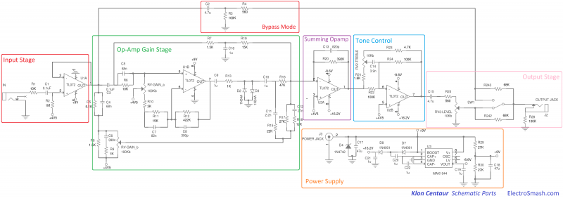
    A minor hiccough at this point is that the original Klon Centaur was a chunky pedal and a lot of the klones use modern PCB design to achieve their small footprint. The only tech I have at my disposal is the mighty veroboard and for whatever reason I’ve got it into my head that I want to build it into a standard sized pedal so I’ve got a bit of an engineering challenge. I’ve done a basic layout of the circuit and I think that I should be able to get it right… time will tell.

    So where am I now?
    Well, I believe that I finally have all the components and am just about ready to begin.
    I still need to spend about an hour or so making sure that my layout actually matches the schematic and am hoping to get the first components into the board either tonight or tomorrow night. Once the board is completed I plan to wire up the pots, switches, jacks etc. and test that everything works before taking drill to metal and installing. At the moment I have no plans for styling on the pedal. First make it work… then make it pretty. ?

    I had an hour or so to work on this last night and I spend that time verifying my layout and marking it up on my piece of veroboard. The board is 19 strips with 35 holes each... and I am using all of it!
    This is the first normal veroboard build I've done in a while (don't count the power supply section of my amp because that was a very special case) and to be frank I'm a little worried that I've been a bit ambitious, particularly with the space required by some of the capacitors.

    ... yeah, that's pretty tight. I have duplicates of all the components so if I make a mess of this I can give it another go. First step would be to split the power supply off to a separate board and try to mount them one above the other. If that doesn't work I'll shell out for a bigger box.

    I built the power supply last night… and it works. ?

    The layout is a little on the tight side but I managed to get it all in. Fortunately that is most of the bigger capacitors out of the way so I’m hoping that there won’t be quite as much of a bun fight in the main part of the circuit.

    I’m very out of touch with electronics but I find this power supply circuit extremely cool. Using a single chip (and apparently against the manufacturer’s recommendations) the circuit turns a 9V supply into:
    18V
    9V
    4.5V
    GND
    -9V

    The 9V is used on the input buffer and gain stage. After that the summing opamp and tone control stages make use of the full 18V to -9V, with the bias set at 4.5V. This gives a tremendous amount of headroom and means that any distortion you get from the pedal will be intentional from those back to back diodes.
    Another cool side effect is that you can use polarised capacitors for those large coupling capacitors… at least I think, my theory is a little rusty (anyone who knows better, please feel free to chip in). What I do know is that I make my coupling capacitors non polarised by default because the voltage can swing either way, this was reinforced by the fact that the schematic I’m using doesn’t have polarity marked… but then again, it doesn’t mark polarity on anything. So when I ordered my initial components, I bought polyester 1uF caps… yeah, turns out those are big. I’ll post a photo some time… but they would not fit in this box. ? So I checked out some photos of other builds and kits and lo and behold, they were using electrolytic.

    Ahem, got a bit side tracked there. Anyway. Power supply built and working… this weekend it’s on to the main circuit. My soldering is a little rusty so it may take me some time… I’ll keep you posted.

    Made some good progress this evening. I was slowed down quite badly by the component picking, particularly for those that I already had in my bag of tricks and didn't buy for this project. I really should have spent half an hour before I started collecting the parts into a single box for quick access.

    I'm also being a little naughty in that I'm not testing as I'm going along. There are three reasons for this.
    1) I've done a complete layout and am basically building from one side of the board to the other rather than in logical components... so there is nothing complete that I could test.
    2) My signal generator and oscilloscope are all the way at the top of the cupboard.
    3) I'm lazy ?

    I reckon I've got another hour of work on the circuit board itself, followed by one to two hours of routing the wires to the other components and then I should be ready to test. After that (assuming everything works) I'll drill holes and start mounting things.

      For anyone interested in the klon and it’s klones, here is another nice website. https://aionelectronics.com/project/refractor-centaur-overdrive/

      Incidentally, I bought a few different diodes to try in this circuit. I’m not trying to make an exact copy of the original and frankly couldn’t find the specific germaniums so I’ll be trying the bat41 schotty diodes first. If I like how they sound I might just leave it there.

      All components are now on the board... and my eyes are crossing so I'm putting it down for a while.
      My layout requires a fair number of jumpers, particularly for the power supply around the board and to get the panel mount leads in one place to avoid spaghetti in the box. Unfortunately this is going to end up a little on the messy side but it is a side effect of the space constraints on the board.

      Whew, that was an intense couple of hours... but the board is now more or less done. Unfortunately the addition of the 'jumpers' has destroyed the neatness and covered most of the components in a couple of layers of wire... which means that any debugging is going to be a challenge.

      These jumpers are basically of two types. They either take one of the supply voltages to a piece of the circuit that needs it or they consolidate the leads to and from the external components into a central spot to reduce spaghetti in the assembled pedal.

      There are a couple of things that I could have done to make the power wires a bit neater. Firstly, I could have given each of the voltages its own rail running the length of the board (I did this with +4.5V and ground)... but this would have required an additional 3 rails. Secondly (assuming I did the first) I could have given those jumpers the same weight as a component during the layout phase, ensuring they could run in straight lines and not cross any components... but this would have added a good few additional rows. In other words to do it properly I would need a bigger box.

      The leads for the external components are a little more tricky. If I didn't consolidate them then the board itself would be a lot cleaner, but the box would be unmanageable (that might be preferable... this is my first pedal... I don't really know). I can think of a few other options (such as an intermediate board) but they all require significantly more space.

      ... but that's all theoretical. This is what I've built... it looks like it's going to fit and right now all I can do is hold thumbs and hope it works first time (lol) because the other option is too horrifying to contemplate. ?

      I finished the wiring last night.
      Here are all the external components soldered up and ready to be installed.

      And here is the final crows nest. I’m quite glad now that I did group all of the leads on the veroboard, the spaghetti would have been a nightmare.

      I finished the work quite late but still decided to plug it in and see if it worked.

      It didn’t. ?

      The LED turned on but nothing came out the other side. Unfortunately I didn’t have time to trouble shoot so I packed up my took myself off to bed. I mean… what did I expect? It’s a complex circuit, there’s a lot that could have gone wrong.

      Well.

      I got into bed… turned off the light… closed my eyes… opened my eyes… and swore.

      … no, for those with sharp eyes, it wasn’t that I’d forgotten to put the op-amps into the circuit because I did that just after the photo. It was actually the output jack, which I had wired wrong (I can never remember which pin is which).

      Heated up the soldering iron… fixed the problem… and it worked ?

      There is a monstrous amount of 50Hz hum, but that’s only to be expected in an open amplifier circuit like this. I’m really hoping that putting it into the box and earthing it properly will sort it out. If it doesn’t there are a few points of clean up I can do on the veroboard… but not much beyond that… holding thumbs.

      I do have a few things that I need to address before I can start drilling holes in the box.
      The leads to the button are too short, so I’ll need to replace them. In my ignorance I got the input and output jacks swapped around… not an issue unless I want to add a battery… which I do. I put a 10k resistor in series with the LED because I’m not a fan of super bright lights on a pedal… but this is a touch too dim so I need to change that resistor… and of course, I can’t panel mount the power plug with the wires attached so those will need to be sorted out. facepalm

      After I have all of that in place the next job will be drilling the holes and mounting the components, which I’m hoping to get done before the weekend.

      Well... it turns out that my ambitions of fitting this pedal into a standard B sized enclosure were almost comically misguided. I had hoped to attach the circuit board to the floor of the box and the controls to the top... turns out the switch in particular is a lot deeper than I had imagined and it just isn't an option.
      So the project was paused for a couple of days while I sourced a BB enclosure to use instead. One of the advantages here is that I can attach everything to the roof of the enclosure, meaning that the bottom can come off freely... and I might even be able to get a battery in there (maybe).

      I went through a few layouts on Sketchup and settled on the one below because it's tolerances were the largest. I'm not 100% convinced about the off center button, but it does give some space for a little decoration.
      After a little bit of measuring and a happy half hour with a drill press the enclosure was prepared.

      I had to make a few electrical modifications (changing LED resistor to make it a bit brighter, reversing leads to the gain pot... correcting the reversal of the leads to the gain pot, lengthening a couple of leads etc.) but when that was done it fitted into the enclosure rather nicely.

      As I had hoped, the addition of the enclosure has completely eliminated the 50Hz hum the open circuit was prone to. Unfortunately, it seems that at some point in my poking I have managed to break the distortion path to the summing op amp. It still functions as a rather tasty boost but there is no clipping so the oscilloscope will be coming out tomorrow to help fault find.

      I'm also planning on taking the opportunity of the circuit being out of the enclosure to give it a layer of paint. I would quite like to add a bit of decoration to the front and will be investigating options but that probably won't happen this weekend.

      Good news: the wiring problem turned out to be a dead opamp. Swapped it out and it works perfectly.
      Bad news: too much rain today so couldn't paint... We'll try again tomorrow.

        Box is painted a nice clean white in preparation for its simple graphics.

        It also appears that I have damaged one of the terminals on the gain pot (changed the polarity so many times trying to diagnose the dead op-amp that the poor thing is just exhausted). It is working but I'm worried that a decent bump might dislodge it. Probably won't go out of my way to fix it now but will definitely include a new ganged pot in my next electronics order.

        I've also had a bit of time to play with it and it is a fantastically versatile pedal. It goes from a sparkling but potent clean boost to some serious growl and the tone knob essentially functions as a treble boost, that I'm sure will cut through most mixes. It also chains very nicely into my overdrive pedal (TC Electronics Mojomojo). I think that I'm going to get a lot of use out of this.

        The last job is to figure out how I'm going to apply the graphics. I'm hoping to have some time to phone around over the next couple of days.

        if you are interested in trying something you could do at home..
        there is the Modge Podge method,


        Thanks man, I'll check it out. One of the reasons I'm hesitant to do this is that I want the graphics to be simple black on white and I'd rather not see the edges of the paper I'm sticking on... and don't trust myself to cut it neatly enough.
        Still, it's good to have in my pocket if I don't come right with the other things.

        @Yeti
        the nice thing about the Modge podge method, is you gently rubber off all the paper with water, so no paper is left behind.
        basically you use the Modge as a glue to stick the toner onto the surface,

        • Yeti replied to this.