(Log in to disable ads.)

Alright, after receiving some great advice in this thread (http://www.guitarforum.co.za/setup-mods-and-repair/building-a-guitar-case-some-ideas), I've decided to get to it and start building this thang. Huge thanks must go out to all who offered advice in the other thread and especially to Neon Gecko who e-mailed me some very good advice accompanied by detailed descriptions and drawings.

As promised, here are some pics documenting the process. It has to be mentioned from the outset though that I am by no means an expert and I will make plenty of mistakes and probably do a number of things twice or more times. In the end I decided that this was that excuse I needed to buy the router I've always wanted. Similar results would probably have been attainable by simply using a jigsaw but I figured that I'd like to get the four cuts exactly the same and the router was just perfect for that.

So step 1 was to print the design so that it can be cut from a piece of supawood for the routing jig. Here is the image of the design. The blue section is the shape of the base and top of the guitar case. The black line is what I printed and is a line 8mm from the outer edge of the desired shape. I measured the distance from the router's guiding flange to the cutting edge of the bit as 8mm and so printed a line 8mm inside the desired cutting line.


Here is where I made my first mistake. I measured the size of the Ukulele and figured that 1.5cm extra all around should be enough for the plush padding inside the case. The cut was made accordingly and having done it now I'm second guessing that 1.5cm. It might be a rather tight fit. Will have to wait and see.

At any rate, this printout was then glued to a piece of 9mm supawood which would serve as the routing jig.


Let's interrupt quickly just to show the bill of materials - at least for the woodworking phase of the project.

That is:
3 pieces of 9mm supawood, 300x700mm. One to be used for the routing jig and two for the base and top of the case.
2 pieces of 20mm pine, 300x700mm. These will be used as the template to bend the plywood sides.
2 strips of 3mm plywood, 100x800mm. One will be used for the sides of body section of the case and the other on for the neck section.
4 strips of 3mm plywood, 10x800mm. These will be used for the sides of the lid. I think I know how I'm going to do this but it's a vague notion so far and hard to explain. You'll have to wait and see.

OK, so now that the printout is glued onto the supawood, cut it out with a jigsaw.

Lessons learned: Rather cut a little bit further from the line. You can always file or sand the wood down to the line but if the jigsaw blade wanders over the line you're pretty much screwed. In Neon Gecko's sage advice: "You can always take wood away but you can never put it back." I was lucky though and only slightly cut into the line in one place. It might not be a big problem but it does bug me a little.


If you look closely, you'll notice that along the side of the neck section, near the tip (in the bottom left of this image) there is a slight concavity to the cut. I didn't even notice this until I started routing around the jig.

OK, so another thing I'd have to make provision for was the fact that my router bit would not be long enough to cut through a 20mm plank of pine. What I did was to sandwich the four planks together and put the template on top, clamp it all together and then drill a few holes through the whole shebang. It is vital that these holes are drilled exactly perpendicular to the planks. A drill press would have been ideal but seeing as I only have a hand held drill I had to eyeball it. I got it fairly accurate but still think I'd have gotten more accurate results using a drill press. The point of drilling these hole is so that I can fit the template to one side of the pine plank, route down to just more than half the thickness of the plank and then fit the template to the back side of the plank and have it line up exactly with the cut made on the front side.

That extra bit of wood on the body side of the template is simply my way of clamping it down. I didn't have clamps that would reach all the way in so I used a piece of off cut supawood and clamped the template down with that.

I then used short dowels of 6mm diameter to fit the template onto the plank to be routed.

Just important that the dowels don't protrude above the surface of the jig as that would impede the movement of the router sole over the jig.

Now the fun part started. Route along the jig, starting with a shallow cut and progressively cutting deeper. Neon Gecko's rule of thumb seemed to work well that you don't cut deeper than the diameter of the bit. Seeing as I was using a 4mm bit I cut deeper in increments of 4mm.


Here is the cut after I reached maximum depth (13mm). After this I flipped the plank around and attached the template again, using the same registration dowels. Notice at the bottom right of the neck section the cut is ever so slightly concave. I'm still hoping this won't affect the end result too badly.

Lesson learned: After finishing a cut, wait for the router to come to a complete standstill before lifting it up. If you don't, you run the risk of breaking your bit. OK, so the whole thing didn't snap in two but I did lose the very tip of the cutting edge which wasn't the biggest disaster but it did mean the the shaft of the bit was now ever so slightly longer than the cutting edge. This meant that consecutive cuts was a bit harder as the shaft would feel the grain of the wood before the cutting edge cuts it. I'll be more careful with future bits but this one did last for all four planks that had to be cut.

Once the cut is made through the plank, rinse and repeat. The second pine plank was cut in exactly the same way and then it was time for the 9mm supawood planks.

For the two supawood planks the registration holes was probably not required and it would have been more correct, I suppose, to simply clamp the template to the plank and route it without having to drill unsightly holes through the plank. Seeing as the wood will ultimately be covered by vinyl anyway I figured that it wasn't really a problem and I could drill the holes without much reason for concern. Besides, the dowels were a very useful way of fixing the jig to the plank.

And here is the final cut through the 9mm supawood. Of course, it is important to have some other piece of wood underneath the supawood so you don't route into your work surface.


Then, rinse and repeat until you end up with this:


The final step of course is to crack open your hops based beverage of choice as a celebratory libation for making your very first jig-based router cuts. It feels great.

So that's how far I got for now. The next step will be to soak and bend the plywood around these templates. It remains to be seen if the 3mm plywood can actually bend to these curves. I'm particularly concerned about the small curve between the two bulbs of the body but that will have to wait until I get some more time to spend on this.
    Very impressive first attempt at making a jig for a router mate, well done! Just a tip with those holes in the superwood. :applause:

    Cut some of those dowels to around 10mm and bond them into place. When the glue has dried, sand flush with the surface and you should be sorted.

    I'm pretty keen to see if the ply bends to that shape, if so there could be a similar project in my future...
      1 thing to try when attaching the 3mm plywood. Score the back with a radial arm saw or cut off saw where the bends will be.

      This is an extreme case of scoring 18mm MDF to get it to bend. But you get the idea.


      Very chuffed that you decided to do this, mine starts in a week or so........
        Neon Gecko wrote:Just a tip with those holes in the superwood.

        Cut some of those dowels to around 10mm and bond them into place. When the glue has dried, sand flush with the surface and you should be sorted.
        Thanks yes, that's more or less what I had in mind.
        flatfourfan wrote: 1 thing to try when attaching the 3mm plywood. Score the back with a radial arm saw or cut off saw where the bends will be.

        This is an extreme case of scoring 18mm MDF to get it to bend. But you get the idea.


        Very chuffed that you decided to do this, mine starts in a week or so........
        I've been thinking of this from early on but, again, I don't have the tools for it. I can't imagine convincing the wife that now is a suitable time for me to buy a radial arm saw or table saw ?

        At any rate, I have a few ideas. I'll start by just soaking the 3mm ply for a few hours and then try to bend it. If that doesn't work, I might try to score it similar to your method but by using the router. It'll be tedious work but it might just work.

        If that still doesn't work, I've had this other idea which I might try as well - laminating a few sheets of cardboard and bending it to shape while the glue is setting. Come to think of it, one could probably even use several layers of wood veneer and laminate it together this way. Might be a bit pricey though.

        For now I'll just try bending the plywood and see what happens. I probably won't get around to this until next weekend though but it's constantly on my mind ?
          don't write off a stanley knife...............get a moer sharp one, the 3mm ply can be scored with that easily.
            Awesome, I love when there are lots of pictures. If you don't mind me asking, could you mention the expenses so far for those who may be interested in giving this a try themselves?
              21Fretter wrote:If you don't mind me asking, could you mention the expenses so far for those who may be interested in giving this a try themselves?
              Good idea. I don't have it with me now but I did keep the receipts. Will include some costs with the next post. Of course my costs will not necessarily reflect the costs that someone else might incur. I've purchased a number of items, like clamps, extra wood (for trial and error) and not to mention a router, of which the cost may or may not really be considered part of this particular project. I'll specify those when I post the costs though.
                flatfourfan wrote: don't write off a stanley knife...............get a moer sharp one, the 3mm ply can be scored with that easily.
                Yeah, I was thinking about that but I'm not sure how effective that would be seeing as the Stanley knife wouldn't really remove any material. I don't see how just a very thin cut would allow the ply to bend more easily - unless you score it on the outside of the curve?

                The way I see it, correct me if I'm missing something, the problem you have with bending wood is that the inside edge is being compressed while the outside edge is being expanded. By scoring the inside edge as in your picture you remove material on the inside edge so that it can compress. Would it work to score the outside edge (with a Stanley knife) so that it can expand more readily?

                Here's a picture to illustrate the difference.


                I'm not sure I like option B simply because I feel it weakens the wood exactly there where it is likely to snap in the first place. I suppose so does option A but my gut tells me that option B would be weaker. I just don't see how you're going to achieve option A with a Stanley knife unless you cut little V-shaped grooves which would be a right pain in the arse. Also, how do you ensure that you cut deep enough but not too deep? Any ideas?

                Come to think of it, I'm starting to seriously consider doing the scoring with the router. Having to cut V-shaped grooves with a Stanley knife seems like just as much, if not more, effort.
                  Dewald "deefstes" Swanepoel wrote:
                  flatfourfan wrote: don't write off a stanley knife...............get a moer sharp one, the 3mm ply can be scored with that easily.
                  Yeah, I was thinking about that but I'm not sure how effective that would be seeing as the Stanley knife wouldn't really remove any material. I don't see how just a very thin cut would allow the ply to bend more easily - unless you score it on the outside of the curve?

                  The way I see it, correct me if I'm missing something, the problem you have with bending wood is that the inside edge is being compressed while the outside edge is being expanded. By scoring the inside edge as in your picture you remove material on the inside edge so that it can compress. Would it work to score the outside edge (with a Stanley knife) so that it can expand more readily?

                  Here's a picture to illustrate the difference.


                  I'm not sure I like option B simply because I feel it weakens the wood exactly there where it is likely to snap in the first place. I suppose so does option A but my gut tells me that option B would be weaker. I just don't see how you're going to achieve option A with a Stanley knife unless you cut little V-shaped grooves which would be a right pain in the arse. Also, how do you ensure that you cut deep enough but not too deep? Any ideas?

                  Come to think of it, I'm starting to seriously consider doing the scoring with the router. Having to cut V-shaped grooves with a Stanley knife seems like just as much, if not more, effort.
                  Option B would also entail having to smooth out the outside with either filler or fibreglass and one's gonna add unwanted weight with the other adding unwanted cost. Doing cuts with a stanley knife is pretty straight forward, one straight down and the other at an angle.

                  Seeing that you do have the router, I'd consider using a very fine tip and literally taking 1-1.5mm off max and spacing the cuts about 2mm apart. That would actually be the best option.
                    I'm inclined to agree with your theory as option B is concerned. if you consider that the kerf (thickness of the cut) on a table saw is around 3 mm. I can't see a 4 mm straight cut router bit not working. I'd cut 2/3 to 3/4 the way through on the inside of the bend as in example A in you drawing.

                    It could get a little tedious measuring out and clamping for the amount of cuts you are looking at though. I'll mail you plans to a simple jig that may help.
                      a month later
                      OK, I finally managed to find some time to continue work on this case. Before I get going with the pics, let me first touch on the matter of costs. There was a request that I keep a running total of costs. It's difficult really to say which costs pertain directly to the project and which are just generic costs but I'll try to split it up so that the costs of just the material for the project is separate from all the other costs I incurred.

                      So far, I've bought the following, starting with the material:

                      3 pieces of 9mm supawood, 300x700mm = R177
                      2 pieces of 20mm pine, 300x700mm = R130
                      2 strips of 3mm plywood, 100x800mm +
                      4 strips of 3mm plywood, 10x800mm = R63

                      Which brings us to total for materials so far of R370

                      I've also purchased some tools that I'd need for the project. I'm generally short on woodworking tools so I used this project as an excuse to get some stuff that I've needed/wanted before and that I knew I'd need for this project:

                      Router = R500
                      1/2" router bit = R34
                      4mm router bit = R29
                      3mm router bit = R19 (because the 4mm bit incurred some damage and this one was very cheap)
                      Vernier caliper = R150
                      Set of clamps = R146
                      Rasp file = R41

                      Which brings the total of non project specific expenses to R919

                      Next post: Making a jig for scoring the plywood.
                        Alright, so the next step of the project, now that the shaping templates and base and top have been cut, would be to score the 3mm plywood such that it can bend around the curves of the template. Again, our local woodworking guru, Neon Gecko had some fantastic advice to dispense. Thanks Neon! In the end this is the jig I decided to build which I could use to score the plywood with the router.


                        It is a bit "overengineered" as compared to Neon's suggestion but I opted for this one for two reasons; One, it would give me more opportunity to use my newly acquired router and two, I don't really have a proper work bench and this jig would also offer more stability to the wood I'm busy scoring. You'll notice in the pics that the whole thing is eventually clamped to a little step ladder which have so far been my work bench.

                        So basically I had to route out a channel of 300mm wide and 3mm deep through a piece of supawood. I started by making sure that the routing depth is exactly 3mm. I figured this is important as I'd be scoring the plywood 2mm deep, leaving only 1mm of wood. If I got these measurements wrong I could mess up the plywood one time.


                        When I was happy that the routing depth was exactly 3mm I proceeded to route a channel parallel to one edge of the supawood.


                        I then measured 300m further into the width of the plank and routed another channel and then used the router freehand to clear everything between these two channels until I ended up with this:

                        Not as neat as I had hoped for. I clamped the plank to the step ladder such that it was overhanging on one side and this caused the plank to bend down on ever so slightly on that side, making the routing less than perfect. This didn't seem to be a train smash though as the 3mm plywood fit perfectly into the channel.

                        I then fixed a strip of supawood on top of the plank, going across the channel, and making very sure that it is square to the channel.


                        ...resulting in a scoring jig as follows:


                        Next post: Doing the actual scoring of the plywood.
                          With the scoring jig done I was very keen to get started on scoring the plywood. My main concern on this project has always been the bending of the wood for the sides and the results of this step would reveal whether that would work.

                          I've decided to break the sides up into two parts. The easier part would be the neck section of the case and the more intricate part the body section. The following illustration shows the two sections that will have to be bent. I've indicated in blue the parts of the plywood that will be scored on the inside and in red, the parts that will be scored on the outside.


                          Starting with the neck section; Using the template I had cut and having marked the section that would need to be scored, I measured the length from the neck/body join to the scored section, the length of the scored section and, of course, the length of the entire strip.


                          I then transfered this to the strip of plywood so that I'd know exactly where to score and where not.


                          The plywood was inserted into the jig and the first cut made.

                          Of course, before I made this first cut I first made very sure that the router was plunged to exactly 2mm depth. It would be a disaster if I routed all the way through the plywood.

                          I was using the 3mm router bit for these cuts and decided to leave a space of 3mm between each cut. To do this I marked a position 3mm from the scoring channel so that after each cut the plywood could be advanced until that cut lined up with these marks and then the next cut can be made. This picture shows the last cut having been made (and the penultimate cut lining up with the markings).


                          The neck section is done and a preliminary attempt to bend it around the template worked beautifully! Booyaaa!!! I think this might just work.

                          So a similar process was repeated for the body section, first measuring the distances to the various sections to be scored. The biggest difference here is that the entire length of the strip of plywood would be scored but two small sections of it would be scored on the outside and not the inside.


                          And the routing continued. Notice the unscored section towards the left, this section would be scored afterward but on the other side of the ply.


                          And once that was done, this is what I ended up with:


                          Again I did a quick test bend to see if it fits around the template and again, I couldn't be more happy with the results. For pictures of how these strips of ply fit around the template you'll have to wait for the next instalment. The next step will be to glue and or staple these strips of plywood to the base of the case. I'm still unsure what the best method would be for attaching these to the supawood. I am inclined to think that mere cold wood glue might not be sufficient, especially considering the plenitude of splinters left on the scored side of the plywood. I'm thinking of using cold wood glue and then also a staple gun to make sure everything stays in place. Your ideas in this regard will be appreciated.

                          It occured to me today also that I might have another, bigger, problem. At the base the piece of supawood will keep these strips in shape but I'm not sure what I'm going to do to make sure that they don't lose some of their shape towards the top as a result of the internal tension. If anyone has any ideas, I'll be happy to hear them. I'm not sure I understand plywood well enough but one thing I might consider is to soak the plywood before I bend it along the template and then leave it to dry in that shape. Hopefully if it was bent into shape while wet and then left to dry while in shape it will retain its shape better when the template is removed.
                            Very impressive mate, you’re looking like an old hand at this woodworking thing! :applause:

                            As to joining the sides to the base, although cold glue would most probably work well enough, I would rather consider using an epoxy adhesive. Prattly epoxy tubes could work out a little costly over such a large area, so maybe a product called Epidermix (think that how it's spelled :-[) would be the answer. This is available from most hardware stores and is available in relatively small twin-pack sizes. I wouldn't really consider using staples or panel pins in conjunction with the adhesive, as this may split the sides. Rather build a small reinforcing gusset up with the epoxy on the inside of the case. Just a tip: To clean up the scored surface, use steel wool to sand and clean away the splinters.

                            I'm not sure how much space you have to play with between the uke and the inner dimensions of the case? But to ensure the shape of the top of the sides of the case (sheesh this sounds confusing now), maybe cut a hollow profile and bond this to the top as a lip (just make sure that you don’t make the lip too wide that you can’t get the instrument into or out of the case :-[). If you are using foam padding and lining on the inside of the case, add this plis the 3 mm of the sides to the width of the lip for a neat finish.
                              Great to see that you're going the scoring route........impressive so far.
                                You could use kerfing to join your sides, which is used on acoustic guitars to join the top, bottom and sides. And use lots of strips of tape to clamp everything together. I'm sure you could get some locally from a luthier? You probably don't want to wait for shipping from overseas. That would probably be the best option..

                                  AUSUM thread this Dewald!!!

                                  Lerning a few "tricks' here for sure. Thanks dude 8)

                                  Time to get the router out again. On holiday for 3 weeks from Thursday ?

                                  Rock n Roll!!!
                                    Neon Gecko wrote: Very impressive mate, you’re looking like an old hand at this woodworking thing! :applause:

                                    As to joining the sides to the base, although cold glue would most probably work well enough, I would rather consider using an epoxy adhesive. Prattly epoxy tubes could work out a little costly over such a large area, so maybe a product called Epidermix (think that how it's spelled :-[) would be the answer. This is available from most hardware stores and is available in relatively small twin-pack sizes. I wouldn't really consider using staples or panel pins in conjunction with the adhesive, as this may split the sides. Rather build a small reinforcing gusset up with the epoxy on the inside of the case. Just a tip: To clean up the scored surface, use steel wool to sand and clean away the splinters.

                                    I'm not sure how much space you have to play with between the uke and the inner dimensions of the case? But to ensure the shape of the top of the sides of the case (sheesh this sounds confusing now), maybe cut a hollow profile and bond this to the top as a lip (just make sure that you don’t make the lip too wide that you can’t get the instrument into or out of the case :-[). If you are using foam padding and lining on the inside of the case, add this plis the 3 mm of the sides to the width of the lip for a neat finish.
                                    Thanks Neon. I'll definitely check out that Epidermix option. As for the top of the sides, I don't think I'll have enough space between the sides and the instrument for a hollow profile. I'm a tad concerned actually that I might have left myself too little room to play with. One idea I've had was to get a strip of aluminium 3mm thick and about 200mm wide or so, then shape that along the template and use it inside the top end of the sides for structural support. My ideas on exactly how to do that are still sketchy though.

                                    flatfourfan wrote: Great to see that you're going the scoring route........impressive so far.
                                    Thanks FFF. Didn't you say that you had a similar project lined up? How is that going?

                                    makepeace wrote: You could use kerfing to join your sides, which is used on acoustic guitars to join the top, bottom and sides. And use lots of strips of tape to clamp everything together. I'm sure you could get some locally from a luthier? You probably don't want to wait for shipping from overseas. That would probably be the best option..

                                    Yesh, that was my initial plan when I has still planned on making the base out of 3mm plywood as well. Now that the base is cut from 9mm supawood I feel that there should be enough surface for the sides to find purchase. I'm sure this ekrfing join would still add strength to the case and it's probably not a bad idea but I imagine the epoxy gusset that Neon Gecko suggests might serve the same purpose. Glad you posted this though because now at least I know what it's called. You should have seen me trying to explain this to a dude at Timbercity ?
                                      deefstes wrote:
                                      makepeace wrote: You could use kerfing to join your sides, which is used on acoustic guitars to join the top, bottom and sides. And use lots of strips of tape to clamp everything together. I'm sure you could get some locally from a luthier? You probably don't want to wait for shipping from overseas. That would probably be the best option..

                                      Yesh, that was my initial plan when I has still planned on making the base out of 3mm plywood as well. Now that the base is cut from 9mm supawood I feel that there should be enough surface for the sides to find purchase. I'm sure this ekrfing join would still add strength to the case and it's probably not a bad idea but I imagine the epoxy gusset that Neon Gecko suggests might serve the same purpose. Glad you posted this though because now at least I know what it's called. You should have seen me trying to explain this to a dude at Timbercity ?
                                      Now that I'm giving it some properthought, you could easily make a long strip of this with a radial arm saw with a thin blade (2 mil kerf should be thin enough) and a couple of meters of window beading (think they make it out of meranti here, and its pretty cheap). Mark at 6 or so mil intervals, set your radial arm saw so that the bottom of your blade is about 1-2 mil from the table and X-rated bobs your uncle ?

                                      edit: I obviously really think this kerfing thing is a good idea.. But truth be told, the last thing you'd want once its all nicely covered up and upholstered is the thing falling apart when you drop it, hurl it or lacklusterly chuck it in the back of your car (I find the uke to be a massively frustrating instrument :-[). +1 on epoxy too. Epidermix is right, its by Sika. If there's a shop with a red man holding a hammer and what looks like a lightning bolt as its logo around you, they're sure to have it.
                                        16 days later
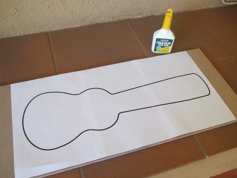
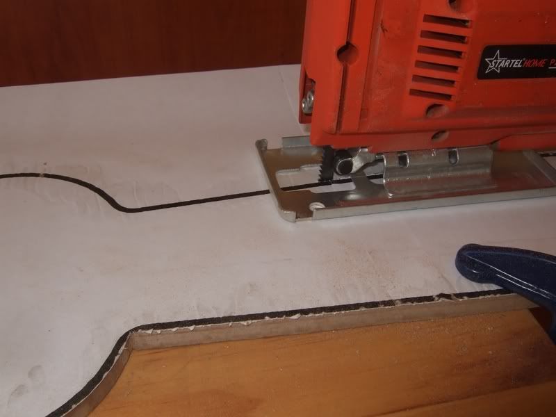
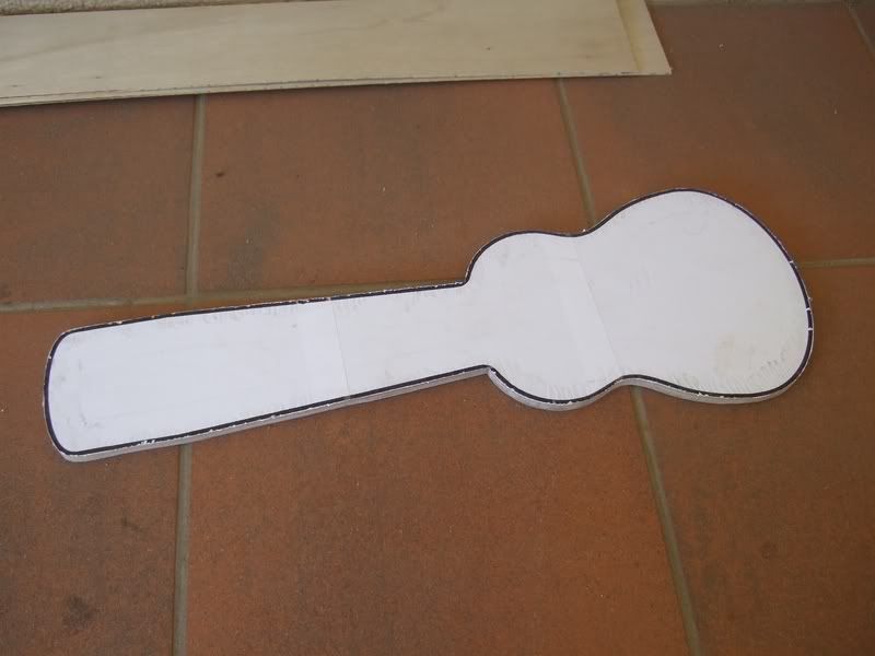
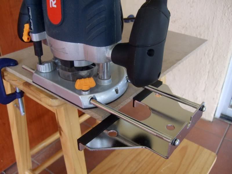
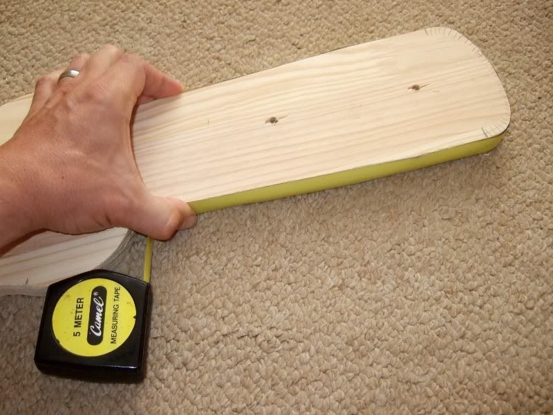
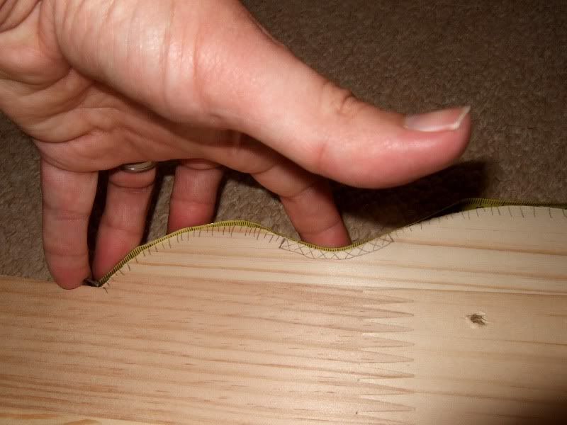
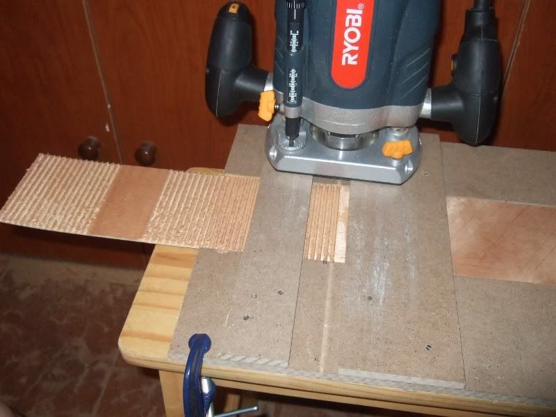
                                        Alrighty, time for some more progress on this project. We pick up the story where the side plywood planks have been scored and ready to be bent around the template.

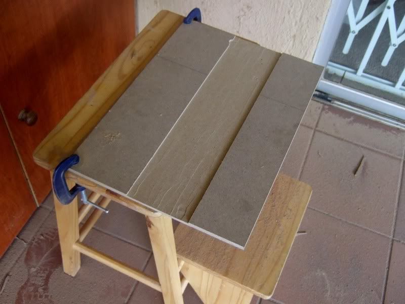
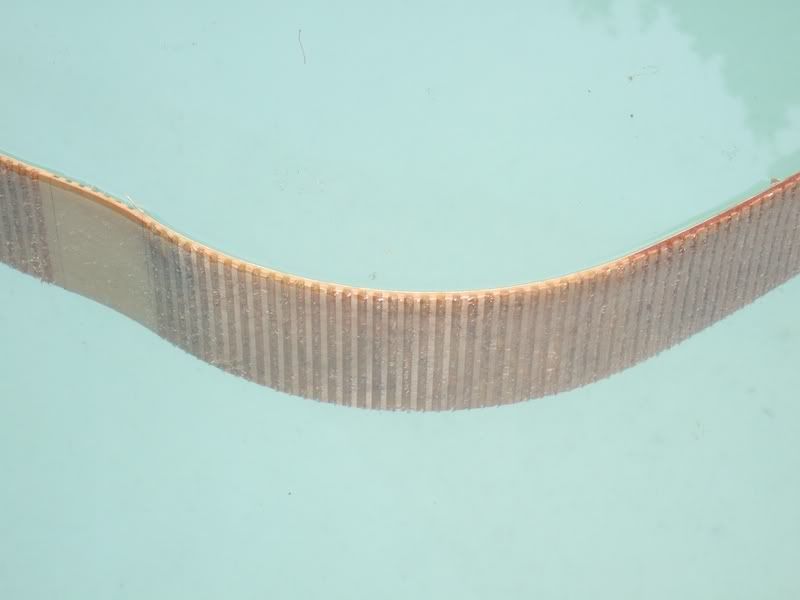
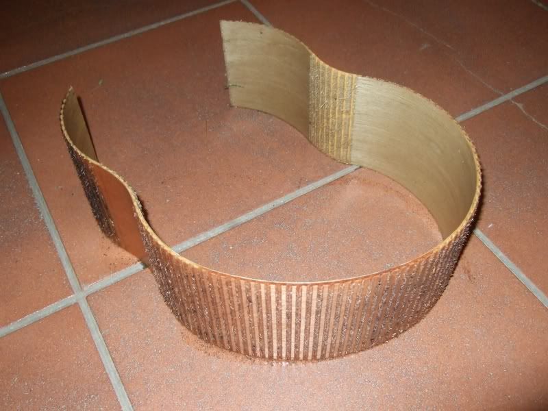
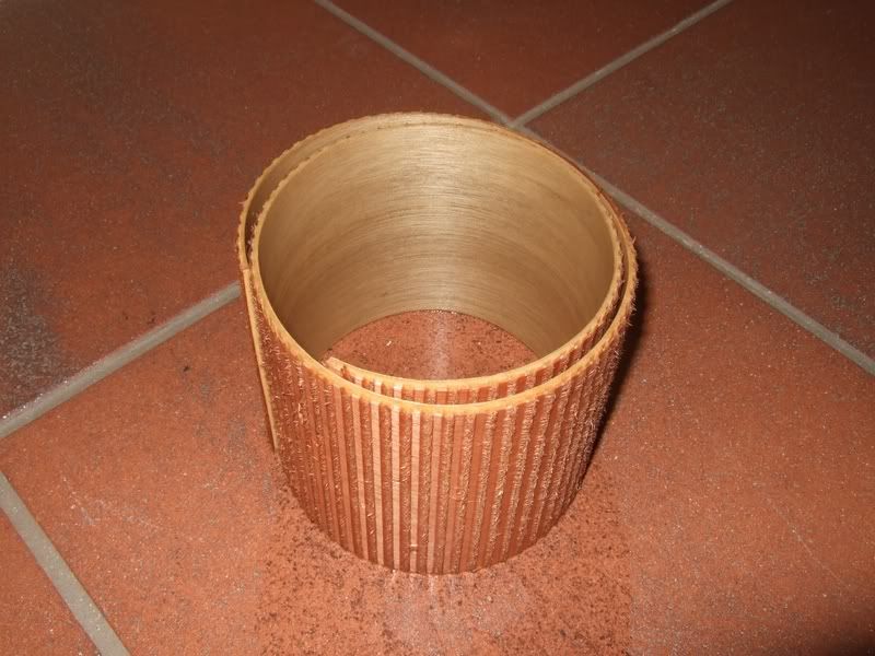
                                        I started by chucking the scored plywood in the swimming pool where I let it soak for 2 hours. The plywood started forming a nice curve along the scored sections. I didn't expect this but I figured it was good as it would make shaping it around the template that much easier. However, the warping took place in the opposite direction as the direction in which I had intended bending it. Notice how the scoring is on the outside of the bend.


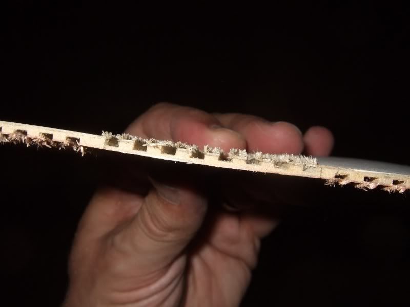
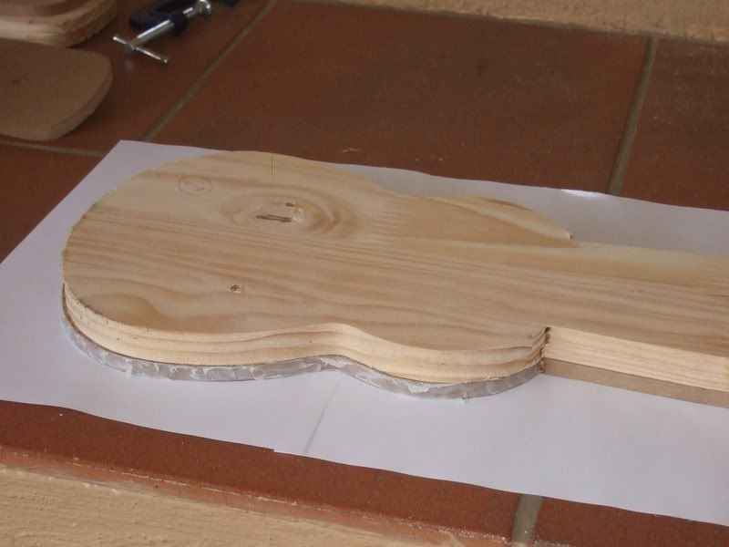
                                        And once I took it out of the water, this is what it looked like


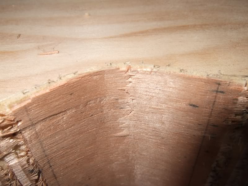
                                        I don't have pictures of it but I bent the neck section around the template, bending it against the newly assumed curve, and it worked perfectly. I figured I'd do the same with the body section because I did want the scoring on the inside of the case. This was a mistake and I realised it as soon as I heard a crack in the plywood when I started tightening down the clamps. I released the pressure immediately and shaped the plywood back to it's assumed curve. Sorry, I missed taking a few pictures but here is a picture of the bending with the scoring on the outside.


                                        This would have worked, but alas, the damage was done and the crack was just too severe. I had to accept the dreaded truth that I was going to have to score a new plank for the body section.


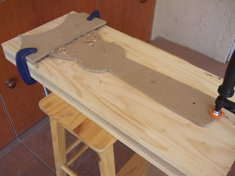
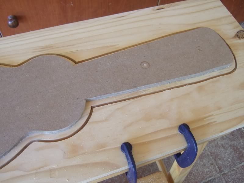
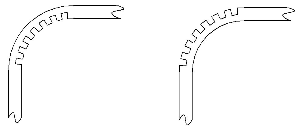
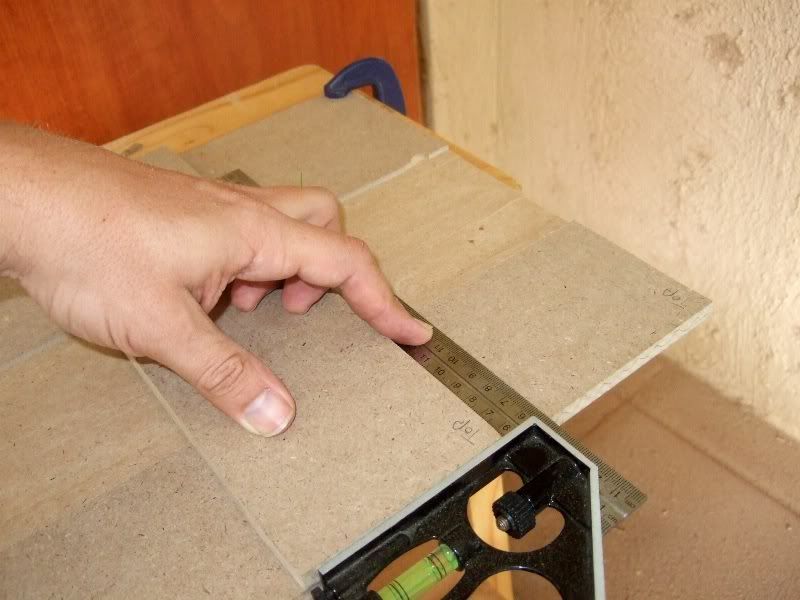
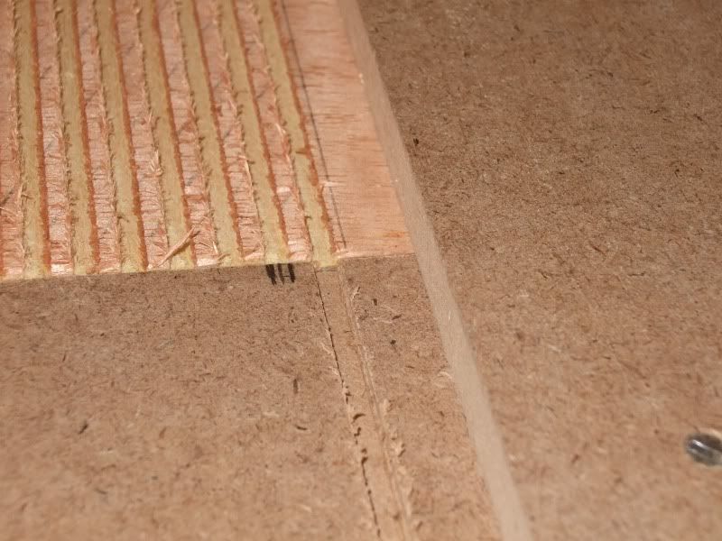
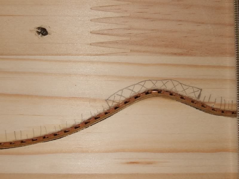
                                        The problematic area, as expected, was the red section in this picture:


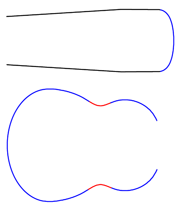
                                        So I decided I'd score the entire plank on the same side this time. It would mean that the plywood would still be bent against its assumed curve for the blue sections but on the problematic red section it would be bent along with its assumed curve.

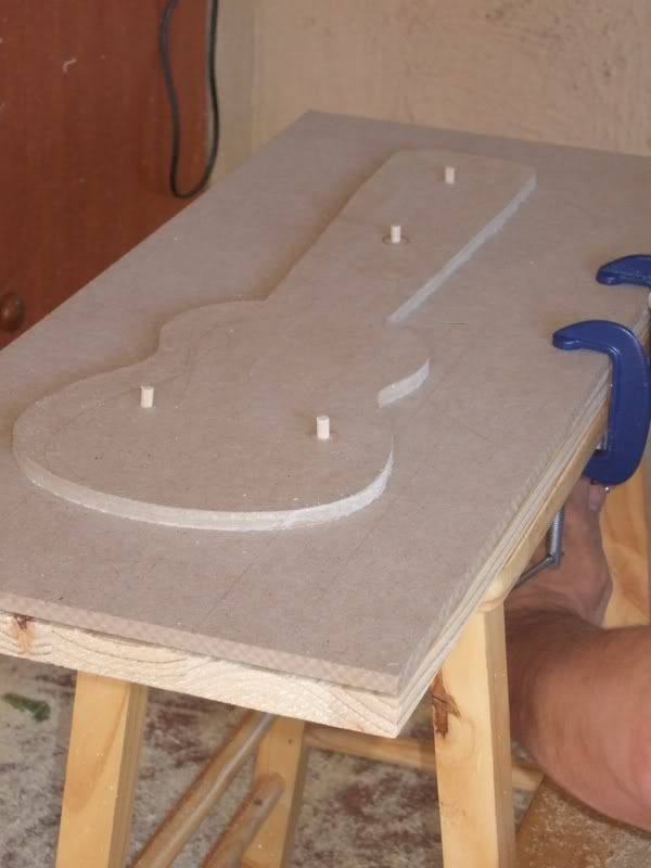
                                        This is what it looked like after coming out of the swimming pool


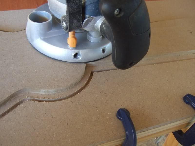
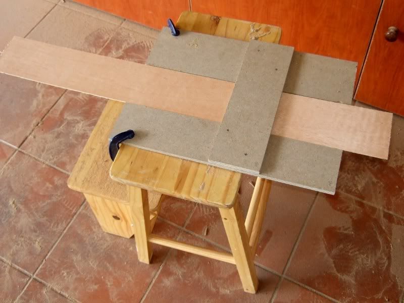
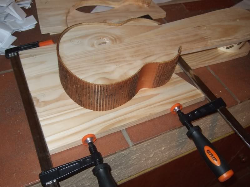
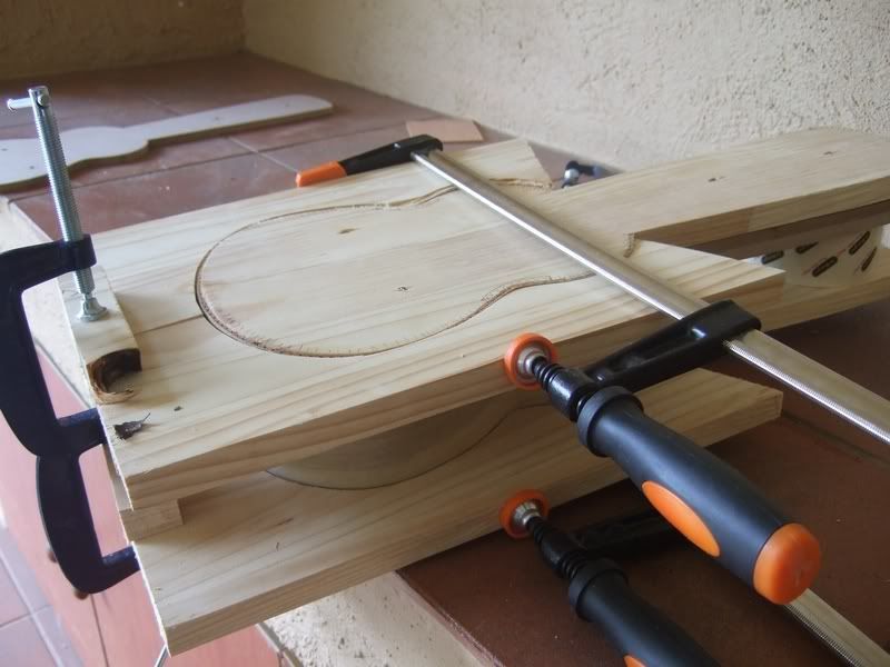
                                        So I bent it around the template and clamped it down. This time, no cracks, it worked like a charm.


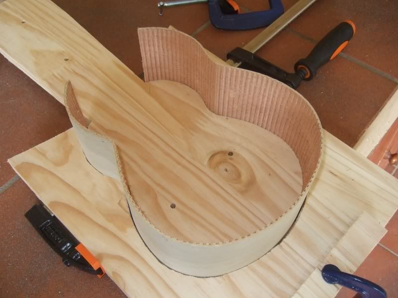
                                        As you can see in this picture, the plywood shaped beautifully around the red section


                                        I left that standing overnight so that the plywood can dry and set in the new shape. Next came gluing it to the 9mm supawood base, using this stuff:


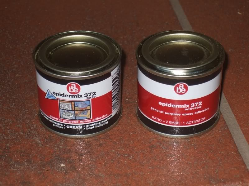
                                        This binary epoxy, on NeonGecko's recommendation, worked perfectly. It's a tad more expensive than some other epoxies but I am amazed at how strong this stuff is.

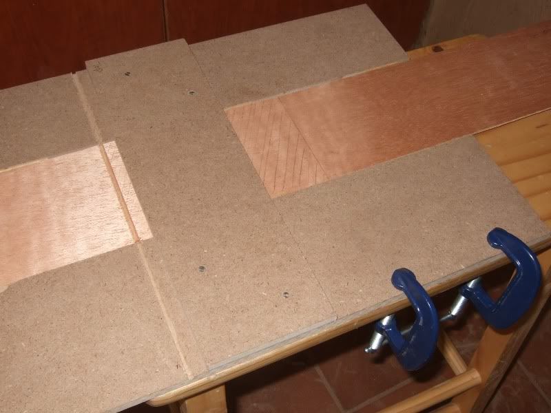
                                        So I applied the epoxy mixture to the sides of the template, laid it down flat on the working surface, put one of the inner templates on top of it and got ready to add the bent plywood and clamp it down with the outer template. I should have noticed at this point, but didn't, that there was going to be epoxy overflow and I'd be gluing the template to the base as well :?


                                        So I continued to clamp it all down and left it overnight again. Note that in this picture, the epoxy is only applied to the bottom plank. The top template is only in place to keep the case as true to it's intended shape while the epoxy is setting.


                                        Like I said, I am amazed at the effectiveness of this Epidermix epoxy and, considering the small amount of epoxy overflow, it took some aggressive wedging to pry the template loose from the base.

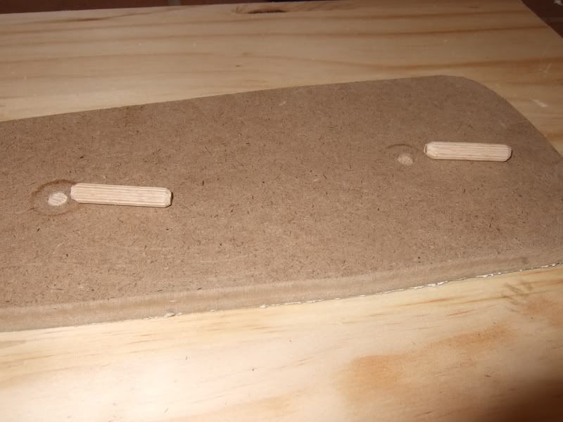
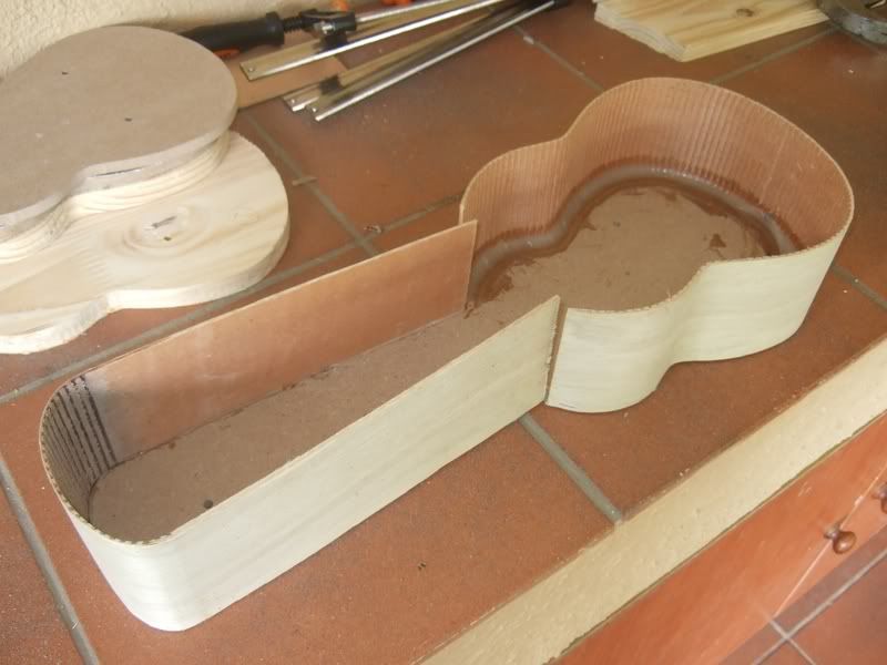
                                        I repeated the process for the neck section, this time not putting the inner template directly on top of the base and after another night, this is what I got


                                        Things are starting to take on shape nicely. Using a plastic spoon, I applied a gusset of epoxy to the body section. I'll do the same for the neck section but haven't gotten around to doing that yet.


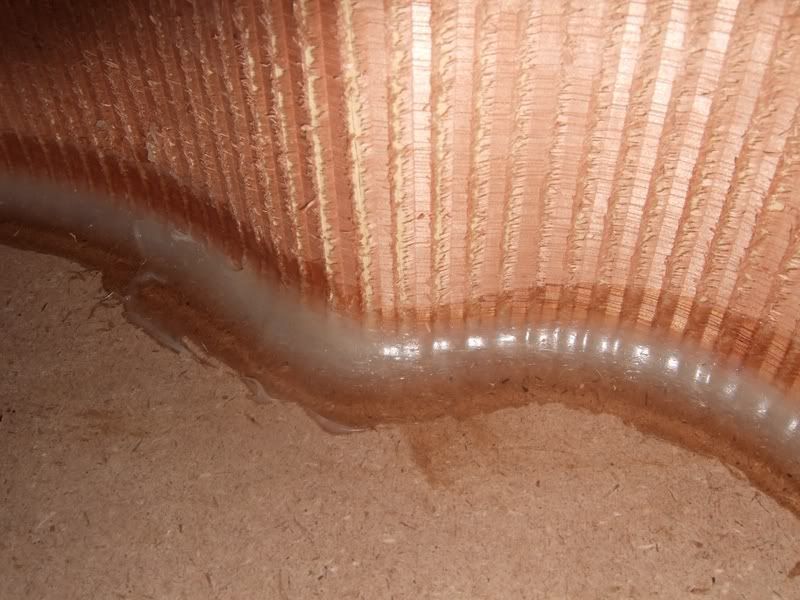
                                        Have I mentioned that this Epidermix is impressive stuff!

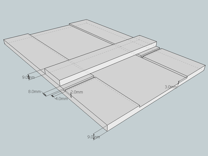
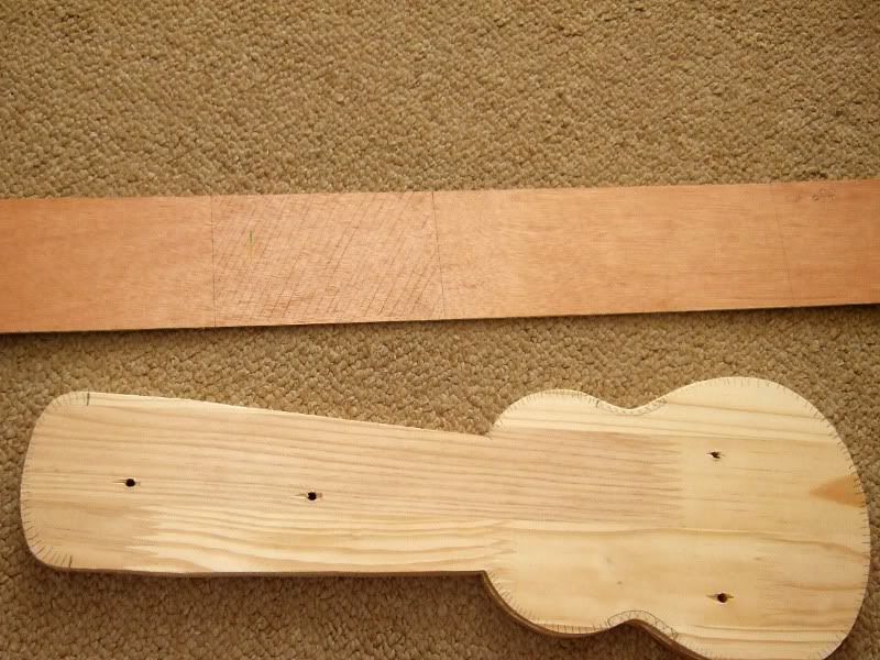
                                        So at this point I need some advice again. As you can see on the second to last image, the plywood for the neck section and body section will now need to be fixed together somehow. When I cut a new plank for the body section having cracked the first, I got my measurements wrong so now there's something like a 4mm or so gap between the body and neck sections. Also, the plywood strips are not standing up at exactly 90 degrees from the base. The neck section is leaning in somewhat while the body section is leaning out. I'm not sure exactly why this is because I clamped the strips down with the templates both at the bottom and the top while the epoxy was setting but I think it is related to the fact that the plywood is not entirely rigid and loses some of its curvature towards the top where it is not supported by a supawood plank.

                                        I'm currently considering the following three options. Would appreciate your thoughts on them or if you have any better suggestions.
                                        1. Simply taping the two together with duct tape. Originally I liked this idea but I'm moving away from it now. If the pieces where flush already it might have worked but considering that there is a 4mm gap now and that the plywood is not at a right angle to the base I don't think duct tape will offer the neccessary strength to keep the plywood in shape. It will simply hold it together and fill the gap.

                                        2. Gluing a strip of paper (or maybe rather thin plastic) on the outside of the join and on the inside of the join with this Epidermix and using enough of it to fill the gap between the strips of ply. Then Clamping the box to the templates again while the epoxy is setting.

                                        3. Finding some sort of thin angle iron (maybe aluminium) that can be bent open somewhat (the join is not exactly 90 degrees, more like 110 degrees), putting it on the inside of the join and riveting the plywood to that.

                                        I'm leaning towards number 2.

                                        Also, while the plywood shaped nicely around the base, it still loses some of its curvature towards the top (open part) of the case. I knew this was going to be a concern and I was hoping that I'd stumble on inspiration during the course of the project but so far I haven't. The best idea I've had so far would be to find a strip of aluminium that's around 3mm thick and 10 to 20mm wide, bend this strip around the template and use it as a stiffener on the top edge and inside of the case. It's important that I find some sort of a sollution to this problem as there will be no way to make a lid that fits nicely over the case if the top end of the case does not conform to the same shape as the bottom end.

                                        So, the floor is open. Fire away with your brilliant suggestions pelase. ?