I did probe the circuit, after the previous post, but never posted the results. Life...
I checked with the new JJ EL84’s, the original Chinese 12AX7’s, and with a JJ 12AY7 in the pre-amp socket, JJ 12AT7 in the splitter.
With Eskom supplying 226 to 229 VAC, the B+1 ran at 338 V, B+2 at 329 V, B+3 at 309 V.
The JJ EL84 measured:
Pin V DC
1 NC
2 Grid 1 0.16
3 Cathode / Grid 3 10.57
4 Heater 0.04 VAC
5 Heater 6.5 VAC
6 NC
7 Plate 321
8 NC
9 Grid 2 (“B+2b”) 313
The pre-amplifier section probed as follows:
Original Chinese 12AX7
(One half is a gain stage, the second half is a cathode follower to the tone controls)
Pin V DC
Gain Stage
1 Plate 1 124
2 Grid 1 0?
3 Cathode 1 0.89
4 Heater 13.27
5 Heater 0
Cathode Follower
6 Plate 2 190
7 Grid 2 124
8 Cathode 2 122
9 Heater ground 6.5
JJ 12AY7
Pin V DC
Gain Stage
1 Plate 1 103
2 Grid 1 0
3 Cathode 1 1.2
4 Heater 13.1
5 Heater 0
Cathode Follower
6 Plate 2 188
7 Grid 2 102
8 Cathode 2 102
9 Heater ground 6.5
Phase Splitter- original Chinese 12AX7
Pin V DC
1 Plate 1 175
2 Grid 1 29
3 Cathode 1 43
4 Heater 13.3
5 Heater 0
6 Plate 2 173
7 Grid 2 31
8 Cathode 2 41
9 Heater ground 6.6
Phase Splitter 12AT7
Pin V DC
1 Plate 1 155
2 Grid 1 38
3 Cathode 1 57
4 Heater 13.3
5 Heater 0
6 Plate 2 156
7 Grid 2 38
8 Cathode 2 58
9 Heater ground 6.5
The schematc specifies a ¼ Watt plate load resistor for the 12AX7 gain stage valve. If my calculations are correct, the original 12AX7 draws 0.7 mA through that 100 kOhm resistor, and the JJ 12AY7 draws 0.86 mA. My calculations show the ¼ Watt should still last a while. This resistor is not surface mount, it is a normal axial lead resistor. The 10 kOhm resistor above it, handling the cathode follower current as well as the gain side current, is just a tiny surface mount item. Go figure.
The 12AX7 splitter valve drew 0.47 mA, and the JJ 12 AT7 draws 0.6 mA, measured over one plate resistor (a tiny little 100 kOhm surface mount thingie).
The JJ 12AY7 and 12AT7 valves do put an extra load on the power supply system.
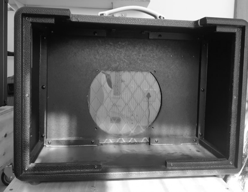
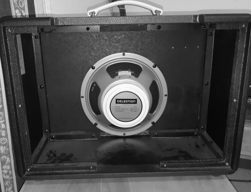
The compact cabinet does have it’s drawbacks. A bit of the speaker is shrouded at the top.

I assembled the amplifier with the JJ 12AY7, 12AT7, and EL84 tubes, a new Creamback speaker, with a speaker lead to the back panel jack.

Initial impression was the gain is less, the tone is not as fizzy as before. And a Top Cut control would be nice.
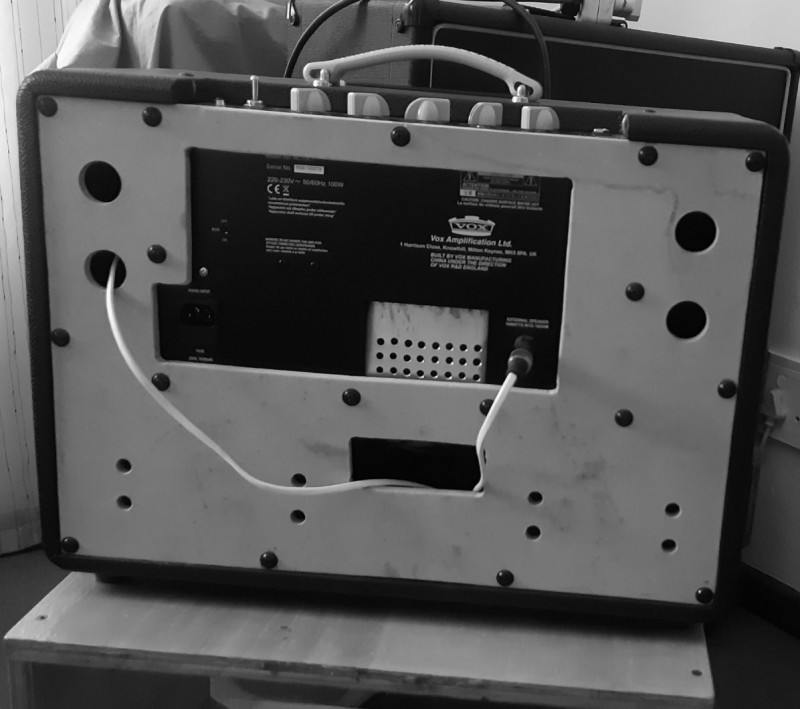
I eventually kicked myself into gear and drilled/sawed the replacement back panel. With that huge chassis plate taking up so much area, “open back” becomes a rather relative term.
The back panel is not sealed against the steel chassis anymore, more of that steel plate is exposed to ambient air, and the cooling intake area is much more than standard. I shall test it for tone like this for a while, then decide if I cut the two extra openings where the corner holes already exists, before final finishing.

What I need to do, is find a way to put vent holes in the top rear to help the PCB and pre-amplifier valves to stay cooler. The standard setup is sure to lead to a “dead” pocket of hot air right in the top rear corner of that chassis. It does get quite warm in use, and some better airflow there can only help.
OK, that was the simple stuff.