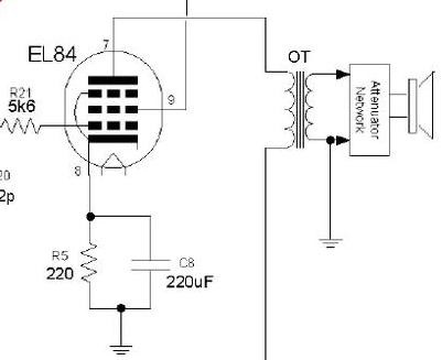
My “ideal home amp” research turned up a schematic of the VOX AC4TV, a single ended 12AX7 - EL84 design, claimed 4 Watts, with a 16 Ohm speaker specification.
The official (?) schematic notes “5K PRIMARY IMPEDANCE”, but also notes “16 ohm turns ratio 35:1”. A turns ratio of 35:1 reflects a primary impedance of 19600 Ohm?
One owner measured the output transformer, reporting a primary impedance of 10 000 Ohm, expecting 5000 Ohm for a single EL84. He advocated the use of 8 Ohm speakers. He also mentioned that the output transformer is physically much larger than comparable amplifiers’.
The amplifier has a built-in attenuator between the output transformer and the speaker, with a rotary switch for 4 Watts, 1 Watt, ¼ Watt.

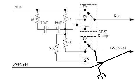
These pictures for the output section might have been drawn from analyzing the circuit, to build a replica. The wiring of the attenuator does not follow that of the official schematic.

The L-pad type attenuator shown with the above does not look like it work for a ¼ Watt setting. I am not convinced about the earth connection from the “Green/Yell” either.
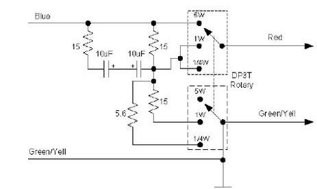
On the official schematic, the attenuator wiring is as follows:

This version looks like adding series resistance to the speaker, likely to reduce output power, as well as bleeding signal to ground, further reducing volume (like a volume control between the transformer and speaker?). Not sure how the capacitors work, must be a high pass filter, to avoid darkening the tone when using the attenuator?
Questions:
Adding series resistance to the speaker, if the primary impedance of the output transformer is already higher than recommended, is not good for the output transformer?
What does the impedance look like with the grounded resistors on the 1 and ¼ watt settings?
Expert opinion on the pro’s and cons of this “attenuator” design?