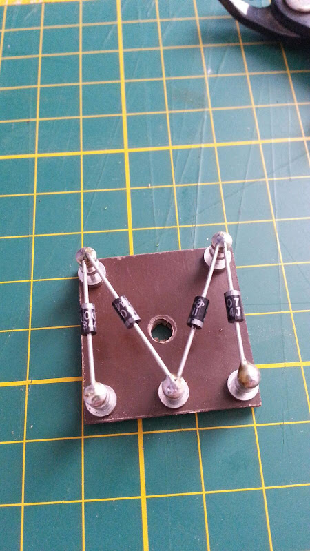
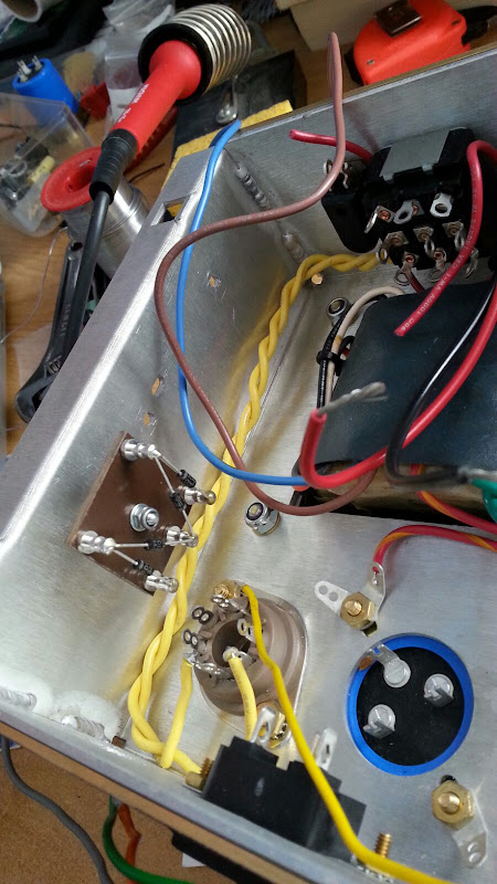
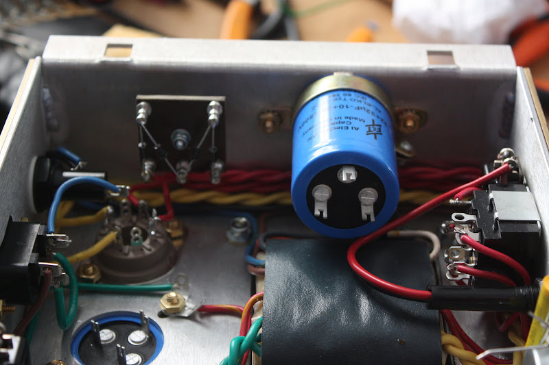
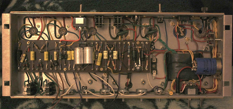
I wired the rectifiers to the switch but I haven't soldered anything yet. The top right solder tab on the pic is where the bias supply is going to be tapped. I still need to install a resistor of some unknown size between that tab and the centre tab below it so that the bias supply voltage can be lower when the switch is set to valve rectification i.e. the centre tab and the top tab (as you see it) is connected to each other when the amp is set to solid state rectification and the bottom / centre tabs are connected when set to valve rectification. The centre tabs gets the high voltage supply. So when the valve rectifier is active, that supply still has a path to the bias supply through the resistor (its not there right now), when the solid state rectifier is active the resistor is short circuited.

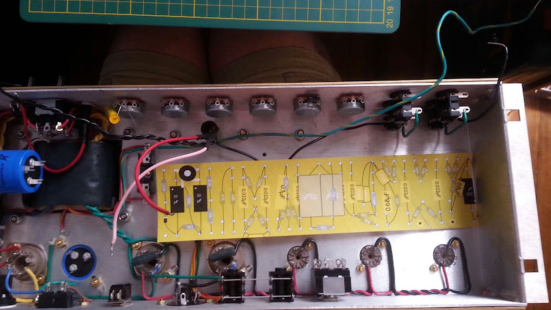
Here's another angle.

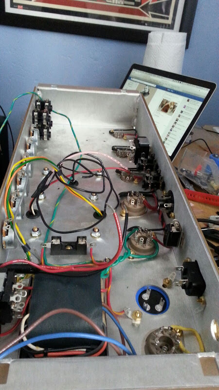
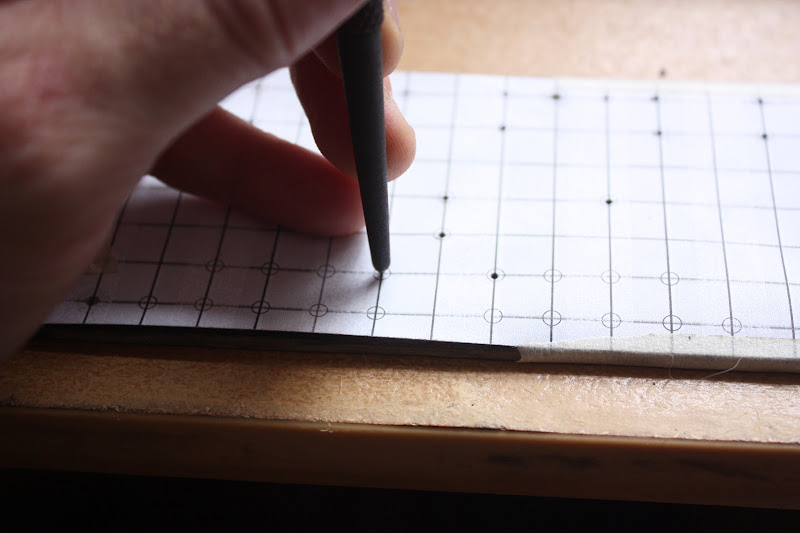
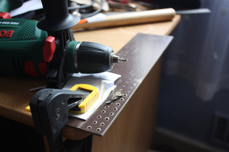
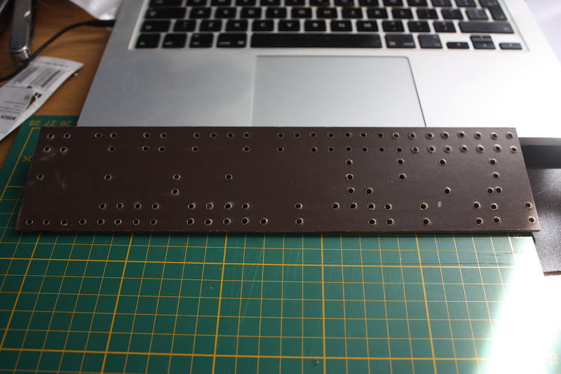
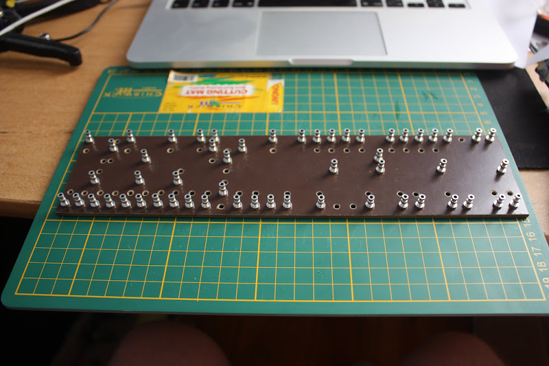
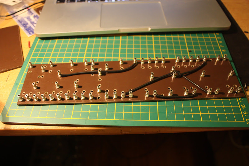
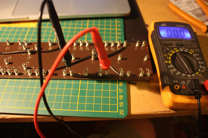
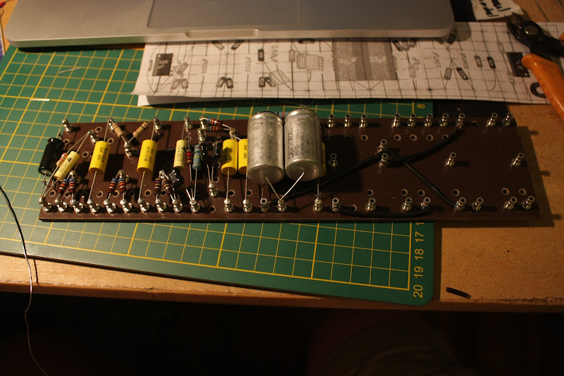
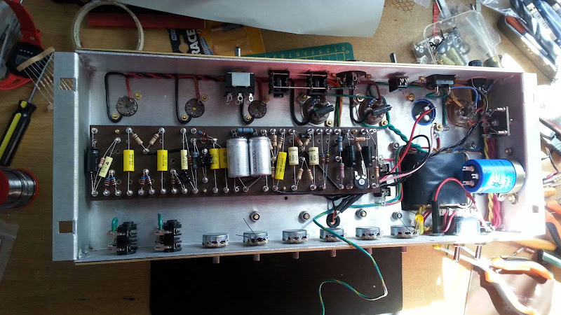
Tomorrow I will add more things to the valve sockets (screen stoppers, plate resistors, bias resistors), wire the jacks, impedance switch, mains fuse, choke and output transformer then I'll start the turretboard. Once I've made sure the layout is fine and have actually MADE the turretboard (drill, install turrets) then the rest will go quite quickly. Its the pondering, planning and measuring over and over that takes so long.