OK so after some heavy work, I got the power transformer mounted. I also mounted the internal fuse holder and the 50µF-50µF can capacitor (That blue thing with the 3 pins).

Now, I need to mount another can capacitor in here since the bottom left-most hole is taken up by a valve socket (in a JMP there are 2 can capacitors next to each other here), you'll notice that there are 2 holes on the left short-side of the chassis. I could have used these however, I also need to somehow mount the solid state rectifier somewhere, so I decided I'll put the rectifier near the valve rectifier and move the can capacitor towards the power transformer.

OK here it is mounted already and I'll use that hole there to mount a piece of turretboard with the rectifier's diodes.

Next, I checked to see if the 3PDT switches would fit, alas I got this:

I removed the nut from the switch and rearranged the wires a bit and now I have this, much better!

Those red wires are the high voltage secondary taps and they need to connect to that switch, I'll loop them around the PT and back to the switch so they can go on straight onto the tabs (and then I can shrink wrap them too).
Test fitting all the pieces is a good way to find problems sooner rather than later. The hole in the faceplate is too small for the fuseholder, for instance, I'll drill (carefully) the plate's hole a bit larger.

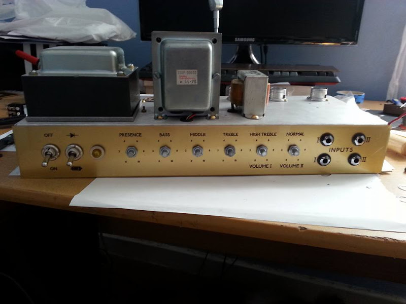
Here I've made sure the other hardware fits nicely and marked the two extra holes required for switches, which I then drilled. The amp model name and 'serial number' was hand drawn by my fiancé. Nice ?

This is as far as I got. The chassis as it stands there weighs about 8kg so its pretty hard work handling it. Combine that with the heat in Cape Town and I'm in serious need of some electrolyte replacement therapy now :goodtimes:
More tomorrow. I think I'll try and finish the faceplates so that I can install the rest of the hardware. I also need a 13mm drillbit for those 2 switch holes on the back (and probably the faceplate's hole which I'll drill out by hand)