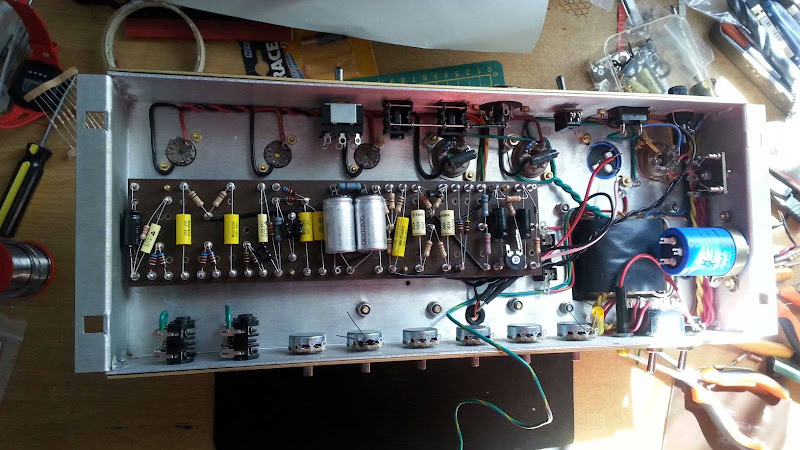
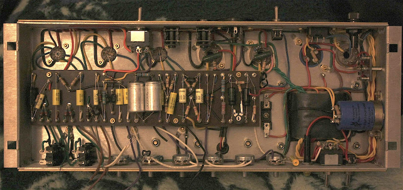
Installed the rest of the hardware on the back of the chassis.
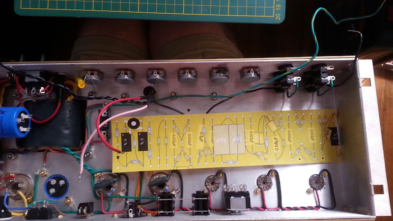
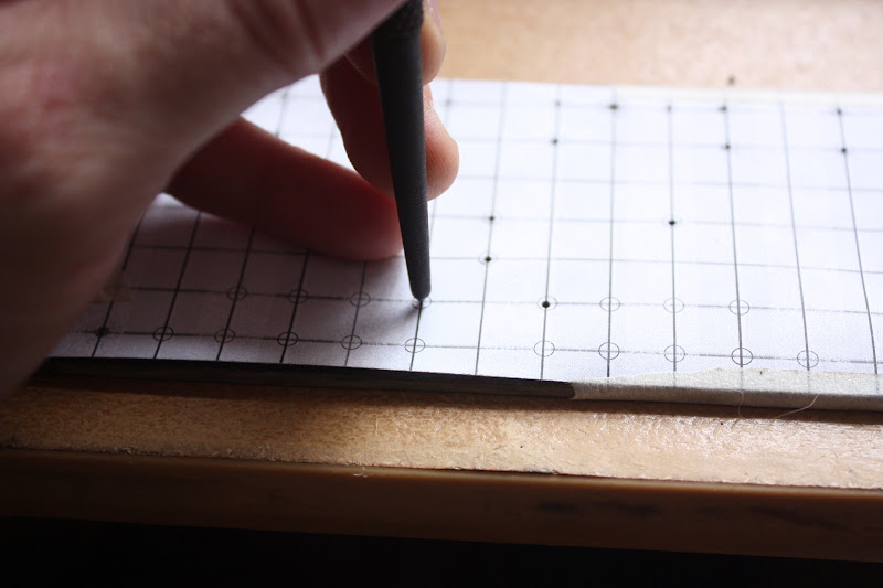
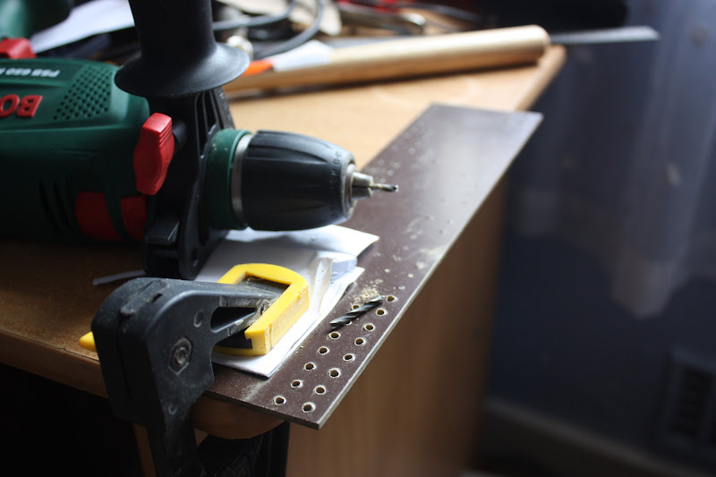
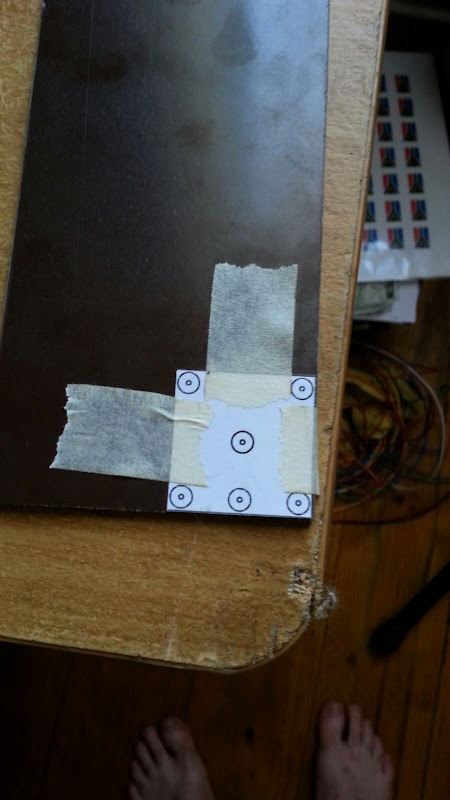
Next thing I wanted to do was build a little turretboard for the diode rectifier, so I made a drilling template.
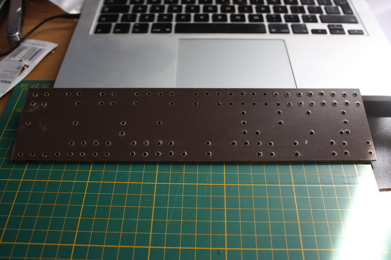
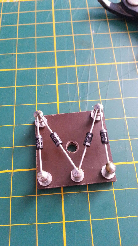
I then installed the turrets and soldered the diodes onto them. The bottom left and right turrets gets connected to the high voltage taps on the power transformer and the bottom centre turret is where the rectified voltage appears. You only actually need two diodes for this to work but I'm using two in series per side so that the voltage rating goes up to 2000V, this is just a safeguard for my transformer in case one of them decides to fail to a short.
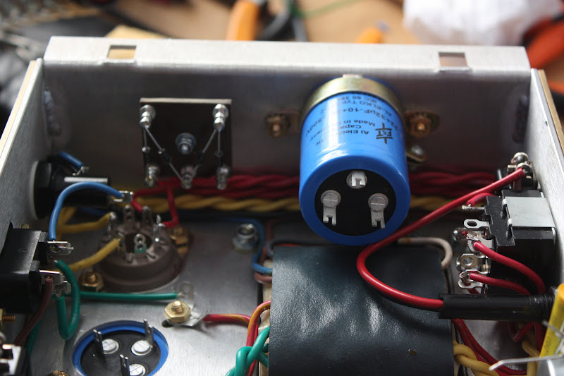
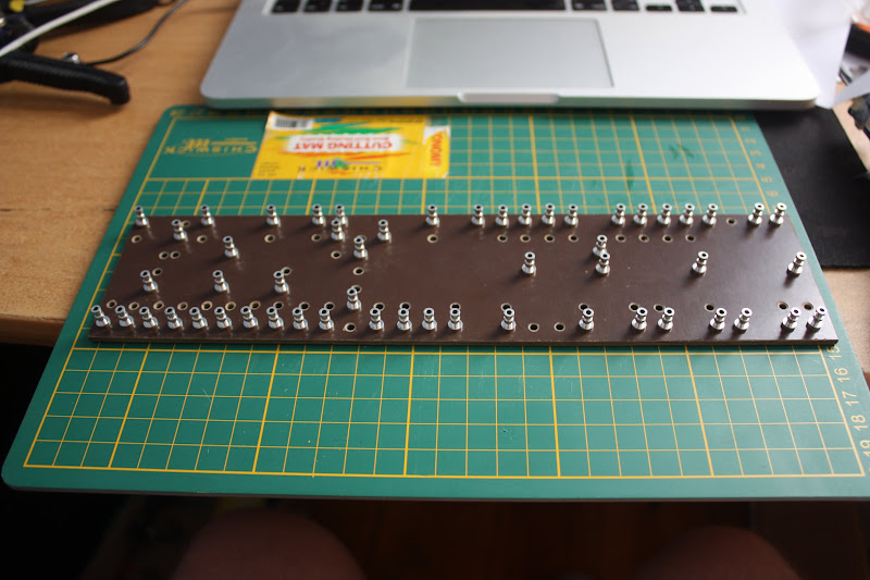
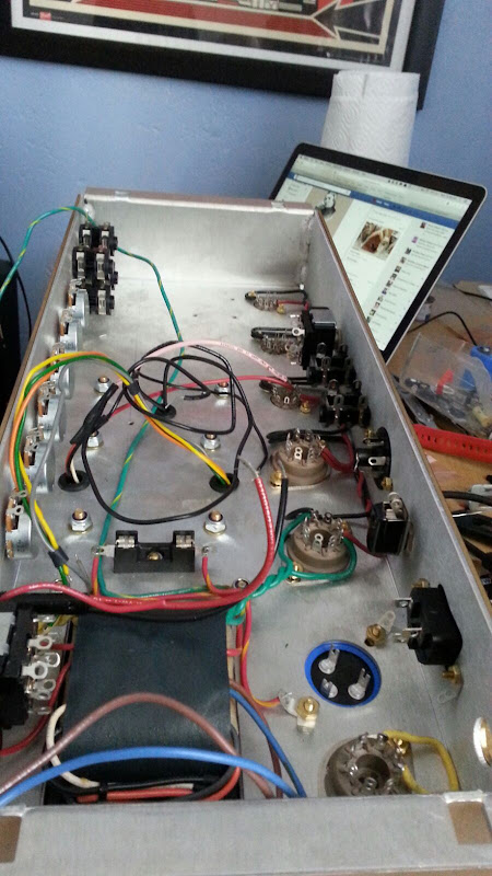
...and installed the rectifier on the chassis. The socket below the board is for the valve rectifier.
Next thing I wanted to do was build a little turretboard for the diode rectifier, so I made a drilling template.
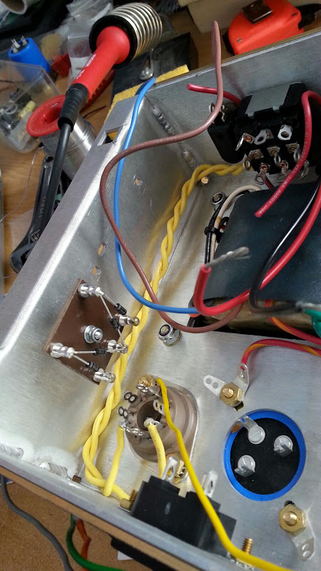
I then installed the turrets and soldered the diodes onto them. The bottom left and right turrets gets connected to the high voltage taps on the power transformer and the bottom centre turret is where the rectified voltage appears. You only actually need two diodes for this to work but I'm using two in series per side so that the voltage rating goes up to 2000V, this is just a safeguard for my transformer in case one of them decides to fail to a short.
...and installed the rectifier on the chassis. The socket below the board is for the valve rectifier.