There are two big advantages to building an amp on an existing chassis rather than doing a completely new build. The first is that it can be a lot cheaper than buying parts individually (especially the transformers… they’re expensive). The second is that you can often use significant portions of the old amp exactly as it is (transformers, power supply, power tubes, heater wiring, etc.).
… of course the downside of this approach is that you are limited to building something that works with the original components.
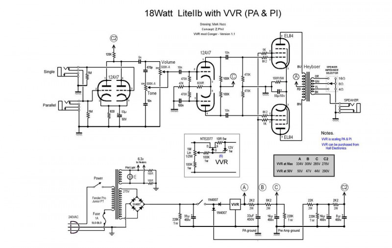
When this amp came up for sale and I noticed the EL84 output stage I immediately thought of a schematic for a 18W plexi with power scaling that I’ve been sitting on for a while.

Other than the power scaling it’s a nice, simple circuit: 1 pre-amp tube (two triodes), long tail phase inverter, cathode bias class AB power amp, solid state rectifier, no negative feedback, and the only controls are volume and tone.
The power scaling is a variable voltage regulator that allows you to adjust the voltage on the phase inverter and power tubes without changing the voltage on the pre-amp tube. In principle this should function as a master volume control with almost no effect on the tone and, from what I hear, they are pretty good.
I used this VVR to drop a little excess voltage on my blackface build and it worked well there.
So, I guess the big question is how well does this amp fit with this circuit?
To start with, the chassis is more than large enough for the job. It’s been designed around the same power amp, so the tube sockets are in place and the transformers are all correctly specced... and frankly that alone is enough.
So what’s different?
- Well, the amp has a tube rectifier, I’ll need to decide whether to just use that as is or remove it and install silicone (it’s a lot easier to go this way than the inverse).
- It doesn’t have a socket for the pre-amp tube but there is an RCA plug in the perfect place that I’ll be removing anyway, so that’s an easy change.
- This amp was in the guts of the radiogram so I’ll need to create my own faceplate but there is a large open surface on the back and there aren’t many controls.
- The amp has an inductor in the power supply, which isn’t called for in the circuit. Again, this is easy to bypass but since it’s there I might as well use it, in principle the only effect will be to reduce noise on the power supply, which is no bad thing.
- … and then of course you get the rest of the circuit, which will have to come out… but that’s only to be expected.
There is a degree of unknown in the power transformer at this stage, since I’m not 100% sure what voltage it will produce. I still need to plug it in and measure.
… actually, on that note I’m making quite a big assumption that everything in the box works. Frankly, at this point I’m just assuming it does and holding thumbs.
One final note on the subject of compatibility. The output transformer is WAAAYYY more than this circuit calls for. From the sounds of things these amps had a reputation for good bass and this transformer is supposed to go as low as 30Hz without significant roll off. For context, most guitar amps go down to 80Hz. This is why it’s so big!
It also has taps on its primary windings to allow ultra-linear connection. Without going to too much detail here, the power to the screen grid of the power tubes is taken through these windings instead of directly through a separate resistor. This provides a type of negative feedback within the tube itself, which is great for keeping things nice and tidy and providing a large clean headroom… but isn’t exactly what you want in a plexi!
I briefly considered turning this into a bass amp instead to take advantage of the bass… or possibly try to design the loudest, cleanest amp I could but in the end I decided to go with the plexi because that is the amp that I actually want right now. 😛