Firstly, a big thanks to @klaasvakie who:
1) convinced me that winding inductors actually isn’t that scary
2) did the heavy lifting from a design point of view
3) actually sourced most of the components for me.
(he was making one for himself and picked up a second set of components for me).
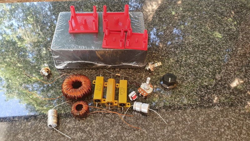
Right… so it’s a simple circuit. The power circuit has three big resistors, a couple of inductors and a capacitor. The lineout side has a smaller resistor and potentiometer and we added an isolation transformer to ensure that none of the DC voltage from the amp gets through to your interface (although this isn’t strictly necessary… as long as everything is working).
The resistors (including the pot) are all very easy, just make sure you get the right power rating.
The capacitor is a little more tricky because it’s bipolar. We couldn’t get one with the right voltage rating so klaasvakie found us an interesting hack that is apparently common in the audiophile world. Basically you take two polarised caps (of double the capacitance) and run them in series, back to back. To be honest, I’m not quite sure why it works, but it seems to…
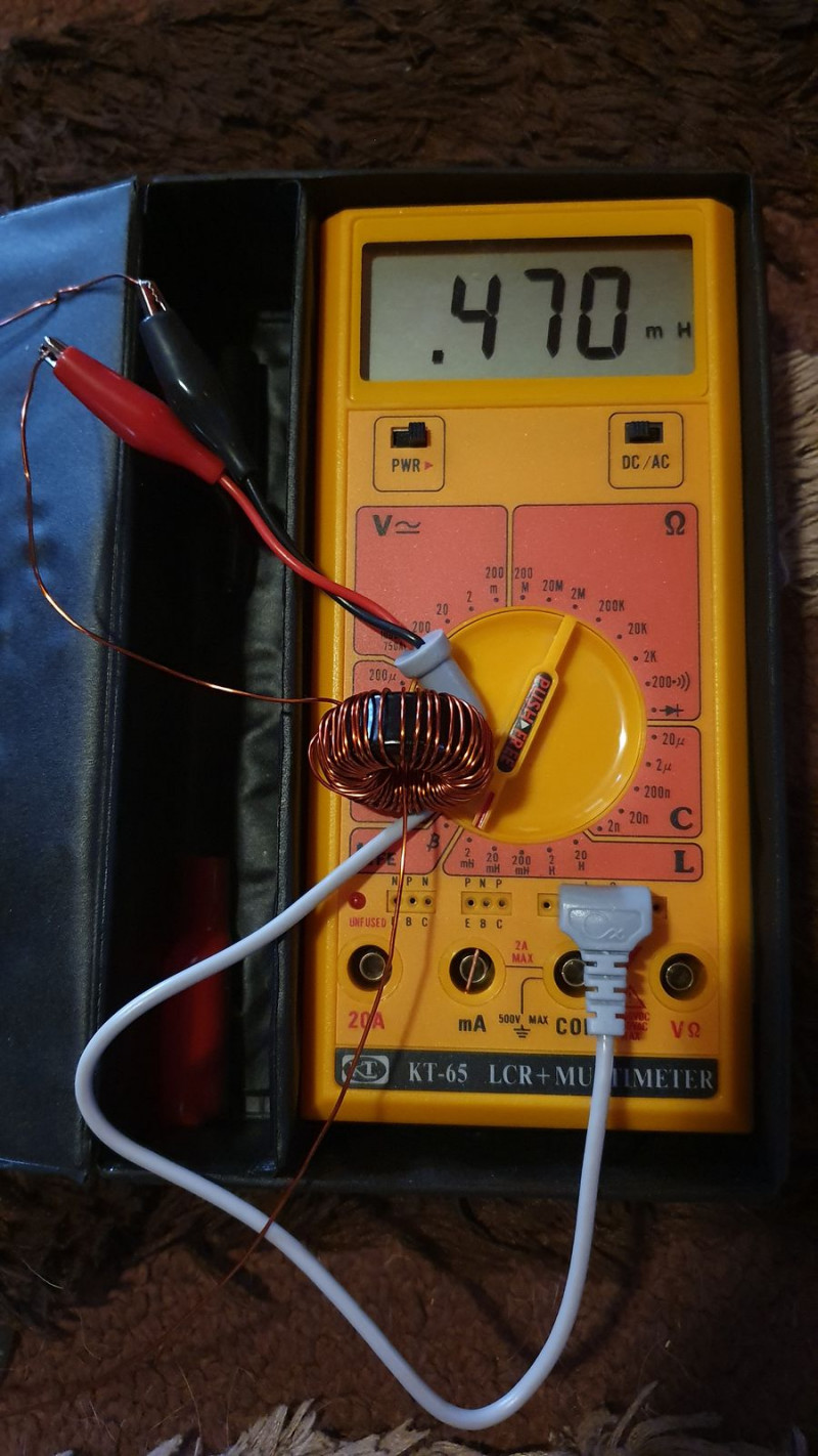
The inductors are where things get interesting thought, because you can’t always just buy them off the shelf and often have to design and wind your own. First step is to select your core, I used klaasvakie’s design here so I don’t have too much to say about it. You then simply find a calculator like this one, plug in your numbers and get a result.
We used two toroidal cores 125u 23.6x47.1x18.5 and 125u 28x14x12 and 0.71mm wire.
The small one was around 50 turns, needing 2m of wire, which was relatively easy.

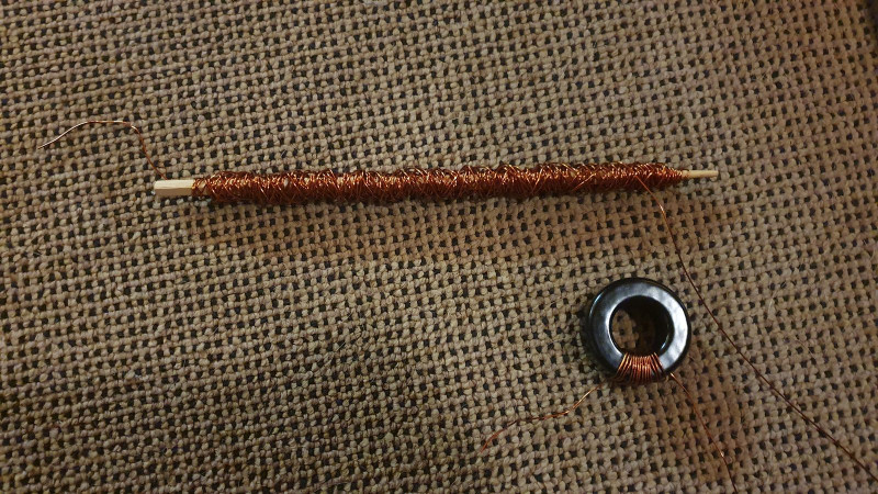
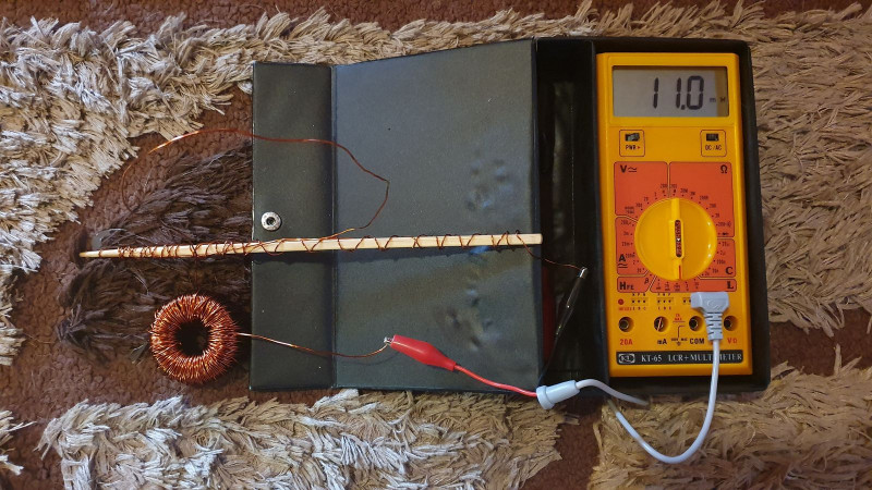
The large one was a little more tricky. It needed close to 200 turns and 12 m of wire. This becomes time consuming because you need to feed the entire length of wire through the hole for each turn. To make this a little more manageable, I wound it around a chopstick first and then used that as a shuttle.

Setting up the shuttle took around 20 minutes and actually winding it took a further hour… really not bad all things considered and it doesn’t require much concentration so you can do it with something playing if the background. It didn’t give the neatest of inductors but it was a lot easier. If I did it again, I’d try to find something a little wider and try to wrap it around length ways instead.

I think that’s where I’ll leave it for tonight. Other than the passive components all you need is a couple of jacks, a knob for the pot and a box to put it in. It is a completely passive circuit so there is no need for a power supply or any indicators.

I'll pick it up again tomorrow if I can and talk about the actual build.