My post of 2August 2020 referred: After all this time, I read you get directly and indirectly heated rectifier tubes. Using the 5U4GB rectifier, a directly heater type, explains my measuring a voltage spike at startup. The voltage spike is probably not good for the other two valves. Or the first filter capacitor, although the dropper resistor should help there. In the interests of valve life, I should use a 5AR4 rectifier, but then I start all over with the B+ that is too high.
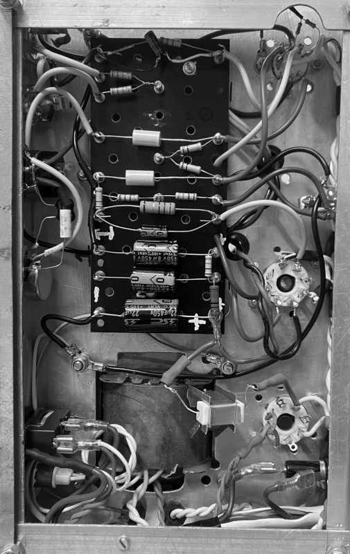
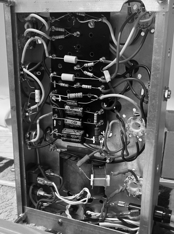
I at long last obtained 560 Ohm resistors for the 6V6 bias resistor. I fitted one measuring 540 Ohm.
I have previously lifted the cathode bypass capacitor on the first stage, not an improvement. I was under the impression I ordered smaller capacitors to use here, but, dang, I did not?
I rigged in an old 10 uF capacitor, while I look for a selection of capacitors. I was thinking 4.7 uF, to tighten up the flab, but may want smaller.
I fitted the 5AR4 rectifier again, and probed the following, with a JJ 12AY7 and JJ 6V6s:
AC at switch 217 VAC
Drop over Rectifier – B+
dropper Resistor 38 V
B+1 350 V
B+2 304 V
B+3 250 V
6V6 valve:
Heaters 6.06 VAC
Plate Voltage 341 V
Grid Voltage 304 V
Cathode Voltage 19.4 V
So, a drop of 19.4 V over the 6V6 Cathode resistor, giving me an idle dissipation of 11.6 Watt. I am happy. The amplifier is still a bit “congested”, but, that is the nature of the beast. Ideally I need an AC supply of 220 - 222 VAC, to lift the heater Voltage a bit, but as is now, it is within the 5% variation.