Hasie wrote:
Although I do not understand half of the technical jargon surrounding this. It is quite interesting. So I would like if you posted the inbetweeners.
If I use too much jargon and you don't understand what I'm talking about then I'm not explaining properly so please let me know in that case. The forum is there for us to learn things. Besides, I don't actually know exactly what I'm doing all the time and explaining will help me understand better ?
The latest saga in this process was the power filtering part and tonestack switch parts. Initially, I wanted to build a JTM45 and I wanted to be able to switch the tonestack (literally the capacitors and resistors attached to the treble, middle and bass knobs) to the JMP values. The JMP tonestack allows more signal to get through so you have more overdrive in the end. It also makes the amp a bit brighter. So, I realised, as per my earlier post, that a 50 watt Bass model isn't that different from a JTM45. So why not build a Bass and Lead model instead? Remember, I bought a JTM45 chassis and most of the parts for a JTM45, and now I've changed my mind. One of the differences between a JTM and a JMP is the power filtering...
The power filtering is pretty simple. The wall gives you AC voltage. This is passed through a rectifier that converts the AC to DC (voltages all positive, say). They work like this:
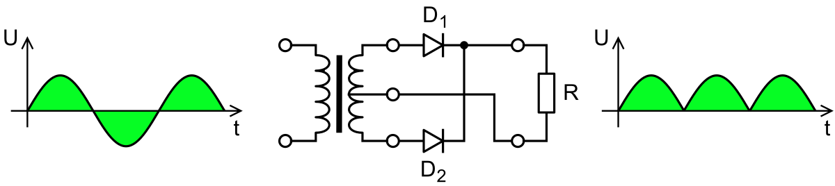
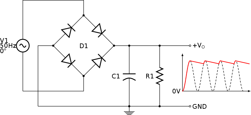
The left graph is what the wall gives you. The right graph is the rectified voltage. As you can see, it ripples (goes down to zero and back up again). The ripples will cause the amp to hum at that ripple frequency so this needs to be removed somewhat (not completely, valves amps sound really aweful if you remove the ripples completely). These ripples are smoothed by the power filtering part of the amp's power supply, and this is what I've been wondering about. If you smooth it a LOT, then the amp feels very stiff and clangy when you hit a chord, if you don't smooth it much the amp will feel a bit looser, not enough and the amp will be too loose and flubby when you hit chords hard. The smoothing works as follows: You have a capacitor to ground. This forms a low-pass filter i.e. lower frequencies gets passed on and higher frequencies gets dumped to ground (the rest of the amp don't see them). It looks like this in a circuit:
I hope this all makes sense so far. In a JTM45, you have 4 such capacitors. In a JMP there is 5 of them. A JTM45 is notoriously underfiltered and have a pretty loose bass response (more flubby on the lower notes). JMPs are tighter. I thought I'd just make a JTM45 with slightly larger capacitor values (more filtering) but the extra one is a curveball. Also, in a JMP, 4 of those capacitors are mounted on top of the chassis, in two cap-cans (Usually big blue or black or yellow tubes) and the other 2 are on the turretboard but in my amp, one of those positions on top is taken up by the valve rectifier, which means I have to mount one of them inside where the solid-state rectifier is going, which means I have to mount the solid state-rectifier somewhere else. This is a bit of amp-tetris I must play now. I think I'll make a little board for the diode-rectifier and mount it next to the can-capacitor inside. Either way, I must install 5 stages of filtering and select values.
OK, but what values should I use for the capacitors? The official JMP schematic says they must be 50µF all round. This seemed quite a lot to me. I then realised the schematic is for a 1970 spec JMP50. After some digging and mailing people I found the values for a 1968 spec JMP (This is the one most people think of as the holy-grail of Marshall sound) and it is quite a bit less. Long story short it turns out that I have all the capacitors for this I need except a single 32µF capacitor.
So now I know the values of the Filters in the power rail and they are as follows:
Rectifier -> 100µF -> choke -> 32µF -> 32µF -> 32µF -> 32µF
This left me with a problem. When those capacitors are drained and you apply a voltage to them, they initially act as a short circuit. So that first one, when you power up the amp, acts as a 0Ω resistance to ground as seen from the rectifier. This means a huge amount of current will flow initially and it decreases as the capacitor charges. The problem is, for a GZ34 rectifier, the maximum reservoir capacitor (That first one) size is 64µF. Higher than this and this 'inrush current' will destroy the rectifier's cathode very quickly. This is not a problem for diodes, they can take a lot of current. So, the solution? On the switch I'm using for switching the rectifier between diodes and valve, I'm going to switch out half of that 100µF (it is two 50µF capacitors in parallel) cap. This means on the valve rectifier setting the filtering would be:
Valve Rectifier -> 50µF -> choke -> 32µF -> 32µF -> 32µF -> 32µF
and on the solid state it is:
Diode Rectifier -> 100µF -> choke -> 32µF -> 32µF -> 32µF -> 32µF
This is quite elegant since it means that on the valve rectifier setting I get a bit of extra 'sag' from the rectifier AND from less filtering, so the difference between the two settings is accentuated and I won't destroy the valve, and on the solid state setting I have the correct rectifier and filtering for a 1968 spec JMP. WIN-WIN!
OK that's probably enough info for now. Ask away if I didn't explain something properly.


